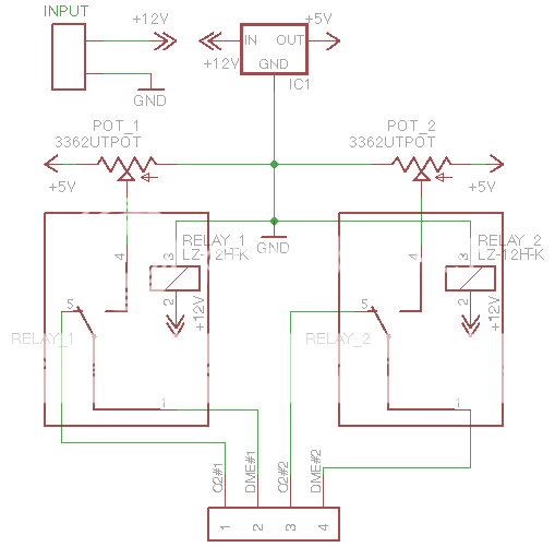
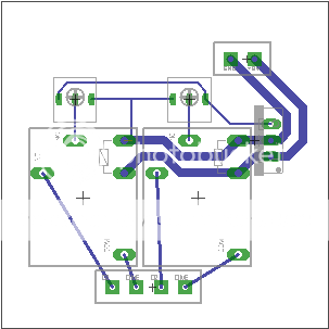
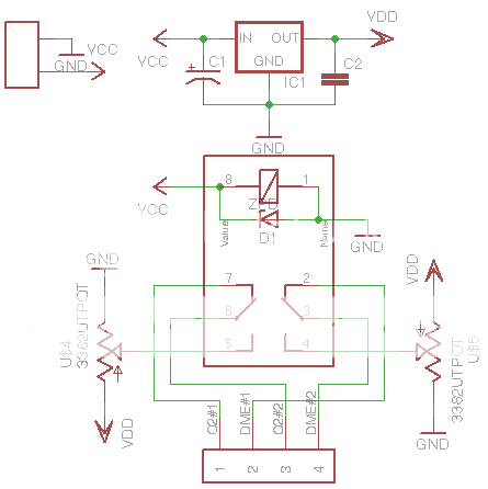
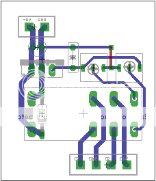
This was my first time using Eagle, and I created this circuit/board. The circuit is used in a vehicle's emissions system. When power is NOT applied to the relay, the O2 sensor signal comes in and then out to the DME. However when power IS applied, a 200 mV signal (through the potentiometer) is generated and sent to the DME (instead of the O2 signal). Trying to keep it small, currently fits on a 2x2" board and will be fitted to a plastic project box.
Opinions are welcome...
Opinions are welcome...
Opinions? OK -
E36 M3: NICE.
Your circuit: not so nice. Trying to create 200mV from 5 using a pot as a voltage divider is folly. The two channels won't track, and ability to precisely adjust it will be non-existent. Use a precision voltage reference and appropriate divider network instead. Also the output of your regulator should have some filtering and you need diodes across the relays for when they open. If you really want to get precise you should separate power for the voltage generation circuit from the relay control. And why not a DPDT relay so you only have one?
Layout: Needs some work. Make sure there's enough room beween the relays and the O2 sensor connector, and fatten up the traces for the switched signals - no reason not to. If you're concerned about aesthetics then route everything on 0/45/90 angles instead of point to point. Also you probably need a heatsink on the regulator so make room for it.
Overall: Unless you really know what you're doing messing with the O2 sensors (presumably to fool the ECU and get a few more HP), check out Dinan BMW instead.
Maybe a little more background into the circuit... There is a "Secondary Air Pump" (SAP) on the vehicle, which the "Digital Motor Electronics" (DME) signals ON during a cold start. The SAP pumps air into the catalytic convertors to speed up their heating. Thus reducing emissions by making the CATs effective quicker.
When the DME signals the SAP ON it expects to see a "lean" condition from the O2 sensors due to the extra air. If it doesn't see a "lean" condition, then it assumes the SAP is faulty and you'll get a "Check Engine Light" (CEL).
The point of the 200mV signal is to temporality fool the DME into thinking there is a "lean" condition. Now it doesn’t need to be exactly 200mV, just in the ballpark.
Mightydub,
I don't understand the 2 channels won't track argument... Meaning you won’t be able to set both to 200mV? They both do not need to be exactly 200mV.
There will not be an O2 sensor connector on the board, just hook up wire leading from the pads out the box... eventually terminating in a connector of some sort.
The reason for the direct signals from the O2 - DME is to keep them as short as possible and equal in length. I guess the same can be done with 0/45/90 angle traces.
Overall this circuit does not mess with the O2 sensors, other than for a brief 30 seconds or so on a cold start it disables them and sends a false signal. Otherwise, the O2 signals go straight into the DME.
OK, now that you explain the background it makes more sense. Still - think through the ramifications of using a pot as the voltage divider. 200mV is 4% of 5V, so at a minimum you'd need a 20 turn pot, and it would be all the way at one end of the range of adjustment. Do you know how much current you need to source to the DME? That will affect the voltage divider values. Is there enough current available from the DME to drive the relays and the regulator, or is it just a control signal? Consider using the control signal to drive a transistor that controls the relays. Make sure you account for all of those issues in the design.
In the layout, you don't need to worry about keeping things equal length, you're talking about DC signals.
In the layout, you don't need to worry about keeping things equal length, you're talking about DC signals.
If it doesn't see a "lean" condition, then it assumes the SAP is faulty and you'll get a "Check Engine Light" (CEL).
How fast is that? The relay contacts need a few ms to get from one side to the other. During that time the DME pins will be floating, i. e. not see 200 mV.
- Status
- This old topic is closed. If you want to reopen this topic, contact a moderator using the "Report Post" button.
- Home
- Design & Build
- Software Tools
- Eagle PCB design opinions (non-audio related)