Gaetan, the simulator directives for your simulation are broken, they are doing nothing right now as they are. Did they not work as expected?
I would use all the signal sources in series. If you have 5 different test frequencies, and you need an input voltage of 100mV, each source will have to have a level of 20mV because they all add up.
When doing 19+20KHz tests, I set Freq to 1KHz for 10 cycles, and then just use a 19KHz and 20KHz source in series. This makes sure there is a complete signal cycle from beginning to end of simulation, so the noise floor will be nice and low. This may be difficult with 5 sources.
For the most realistic result, you should use good models and use a set of simulation directives such as mine. All your models seem to be the crappy vendor models; you should use the models from here, he has all the models you need:
CordellAudio.com - SPICE Models
- keantoken
Gaetan,
I would use all the signal sources in series. If you have 5 different test frequencies, and you need an input voltage of 100mV, each source will have to have a level of 20mV because they all add up.
CordellAudio.com - SPICE Models
- keantoken
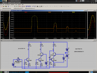
Hello KT
Is it like this ?
I will look at Cordell site.
Thank
Bye
Gaetan
Attachments
Last edited:
Gaetan, it would be nice, but your set of frequencies will not get a low noise floor in LTSpice. Although your sources are set up correctly.
To get a low noise floor, your simulation time must be a multiple of your test frequency's period. This produces full cycles, not cut off in the middle, so there is no DC offset, which for some reason totally confounds the LTSpice FFT. 19+20KHz IMD needs enough time to cover one full cycle of 1KHz, or the heterodyne will be cut off in mid-cycle and will leave DC drift to confuse the FFT.
Your frequencies, because they are so random, will have a very long complete cycle time, if you can even manage to figure it out.
19+20KHz IMD is not hard for LTSpice, because it has a single, short cycle, at 1KHz. With multiple randomly spaced tones like you have used, it will be very difficult to get usable output from LTSpice.
I wish Mike could work out that ridiculous flaw in the FFT.
- keantoken
Kean,
I tried the cordell models with no change in my results.
If you are bored, please try to model a simple cascode circuit and demonstrate that it has lower distortion into a high impedance load than a simple common emitter amplifier. I have had no luck. Distortion should all but disappear!
I will be very interested to see your results!
Gaetan, the simulator directives for your simulation are broken, they are doing nothing right now as they are. Did they not work as expected?
- keantoken
keantoken said:Your frequencies, because they are so random, will have a very long complete cycle time, if you can even manage to figure it out.
- keantoken
Hello KT
My simulator directives are minimal but it's working, I want to keep it simples but if you have few little things that can be ad, I'm open.
I want to do like the Nelson Pass IMD simulation test, but he did used his own software set to do a 7 frequencies IMD test, his test show more about an amp that the standard 19+20KHz IMD test.
So, since I can't use the Nelson Pass personal software set, I want to do it with LtSpice.
Would you have 5 frequencies to suggest me to do a more usable LtSpice IMD test ?
Thank
Bye
Gaetan
Last edited:
Part of the special thing about multi-tone IMD tests is they work well specifically because the tones used aren't closely mathematically related. To do this practically in LTSpice, the tones can't be random or scattered. So LTSpice is not very practical for this test.
I'm not sure how to go about finding a good set of frequencies, but I'm sure it involves finding the least common multiple of periods.
- keantoken
I'm not sure how to go about finding a good set of frequencies, but I'm sure it involves finding the least common multiple of periods.
- keantoken
Actually, SWF, cascodes aren't what they're cracked up to be. Sometimes you just end up worsening the transistor's performance by reducing the Vce bias. A transistor's linearity increases with Vce.
If you can hold Vce constant with current, usually there is a significant decrease in distortion. Cascodes help most in situations where there is a large voltage swing at the collector, such as the VAS of a power amp, because a modulating collector voltage will induce distortion, including the distortion in the collector signal (switching glitches for example in an AB amp).
One important thing SPICE doesn't model is thermal effects. Cascodes improve distortion by decreasing thermal effects, but this won't show up in SPICE.
If your simulation is showing not much improvement I would tend to trust the simulator since I know the models to be of high quality. However the results vary largely depending on application. In a power amp the effect can be good, insignificant or even worse, and this often depends on the VAS device used.
I remember being disappointed like you, when I actually did some tests on cascodes and found they often didn't help much. To get the most out of a cascode you have to pick devices carefully. Often the problems solved by a cascode can be solved more completely by changing the design or the components chosen.
At least with these simple circuits, I don't think you will find a dramatic improvement in specs when using a cascode. However inside certain circuits they can be a large step, after other sources of distortion have been minimized.
Cascodes have a very good reputation, but that is because there is a specific set of applications they work very well in. Current sources is an excellent example. Look up the hawksford cascode and baxandall cascode.
I hope this was accurate.
- keantoken
Kean,
Thanks for your message.
I understand what you are saying however I still have problems believing the simulation. I have set my cascode voltages to well above the saturation voltage at the currents I am using, and I have tried some simulations at 100kHz.
Anyway, I might try lashing up a circuit and running an FFT on my scope to see what actually happens.
Hello
How can we substract, at the output of the amp circuit, the fondamentals of the tones, in a Ltspice IMD test, to have only the resulting IM distortions ?
With a 4 or 5 tones IMD test, it would be easyer to analyse the IM distortions spectrum without having the fondamentals of the tones in the spectrum.
Thank
Bye
Gaetan
Last edited:
HiKean,
Thanks for your message.
I understand what you are saying however I still have problems believing the simulation. I have set my cascode voltages to well above the saturation voltage at the currents I am using, and I have tried some simulations at 100kHz.
Anyway, I might try lashing up a circuit and running an FFT on my scope to see what actually happens.
I just spent a while fiddling around with this. As long as the common-emitter stage was driven from a low source impedance, I couldn't see any improvement with cascoding either. I guess the Vbe non-linearity dominates the distortion, masking the other distortions that cascoding can reduce.
However, with a high source impedance, there is a dramatic improvement with cascoding. This is representative e.g. of a VAS transistor driven from the input stage via a current mirror. Here's a couple of circuits with the results to give an idea.
Warning: I used perfect current sources and infinite capacitors to get the biasing to sort itself out, so the emitter of the first transistor is at about -5V.
Cheers - Godfrey
p.s. Oops, just realised I forgot to change the cascode transistors to Bob's models. Too bad.
Attachments
Godfrey, your results match my experiments. So it seems an amp is unlikely to benefit from cascoding unless it is very sensitive to the Ib of the VAS. This may be bad news for FET VAS. Either way, results are highly variable, mileage will vary, so it's worth testing in many given circuits. One important improvement is the increase in speed, especially for the hawksford/baxandall variations, but you can shoot your foot here too.
SWF, I greatly encourage you to use real transistors for this, better than simulation in this case. It would be of great edification to many of us!
- keantoken
SWF, I greatly encourage you to use real transistors for this, better than simulation in this case. It would be of great edification to many of us!
- keantoken
Thanks guys,
This is interesting. Nelson pass' paper about cascades has a measured example and the improvement was significant, but then again he had just released a cascode amplifier so we can't be sure if his test was completely neutral.
I will try setting up a real life circuit when I get a chance.
Thanks again for your help!
http://www.essex.ac.uk/csee/research/audio_lab/malcolmspubdocs/J10 Enhanced cascode.pdf
jump to the last few pages for the test, measurements
uses 560 Ohm source R, 100 Ohm degen, 10K load
degen is critical to "enhanced" cascode operation
Spice should show the improvement if Zcb nonlinearities are properly modeled the 20K, 50K test freq are way above unmodeled thermal time constant effects
[edit: I am having some difficulty seeing the improvement in a simple single ended sim - I'm pretty sure I've seen cascode distortion imrovement in sim in the past]
Last edited:
frequency sweep
[help=]%[/help]
Hi,
I want to sweep the input over a frequency range.
What is the statement for AC1?
This is what the help page shows. I don't understand what it is telling me.
[help=]%[/help]
Hi,
I want to sweep the input over a frequency range.
What is the statement for AC1?
This is what the help page shows. I don't understand what it is telling me.
.NET -- Compute Network Parameters in a .AC Analysis
This statement is used with a small signal(.AC) analysis to compute the input and output admittance, impedance, Y-parameters, Z-parameters, H-parameters, and S-parameters of a 2-port network. It can also be used to compute the input admittance and impedance of a 1-port network. This must be used with a .AC statement, which determines the frequency sweep of the network analysis.
Syntax: .net [V(out[,ref])|I(Rout)] <Vin|Iin>
+ [Rin=<val>] [Rout=<val>]
The network input is specified by either an independent voltage source, <Vin>, or an independent current source, <Iin>. The optional output port is specified either with a node, V(out), or a resistor, I(Rout). The ports will be terminated with resistances Rin and Rout. If unspecified, the termination impedances default to 1 Ohm except in the case of the Voltage source with an Rser specified or an output port specified with a resistor. In those two cases the termination resistances defaults to the device impedance. Termination values specified on the .NET statement will override device impedances for the .NET calculation, but not for the normal .AC node voltages and currents. That is, the .NET statement will not impose terminating impedances on the network for the normal voltages and currents computed as part of the .AC analysis.
See the example file typically installed as C:\Program Files\LTC\LTspiceIV\examples\Educational\S-param. It recommends using a voltage source, V4, with Rser set the desired source impedance and a resistor, Rout, to set the output termination with a .NET statement reading simply ".net I(Rout) V4." No Rin or Rout values specified on the .net statement and the input/output devices supply default termination values. This arrangement makes the node voltages and currents of the .AC analysis correspond to the network being terminated in the same manner as in the .NET statement.
There is no statement for AC1 I guess. Just add the .net directive to the spice. I will try it out.
Here are my cascode tests. In this case it actually looks like the Early effect errors are combining with the other errors to cancel the second harmonic, making the non-cascoded circuit more accurate.
This effect should depend a lot on the transistors used. In the Hawksford paper he used ZTX653/753, which are medium power transistors, slower and with lower gain. It makes sense that his results were more dramatic because the Ib of the transistors will be larger in proportion to other errors due to low Hfe.
- keantoken
I have no idea. The most important thing I learned about LTSpice is that there are alternatives which work as well, but are easier to use. Here's what SIMetrix looks like.[help=]%[/help]
Hi,
I want to sweep the input over a frequency range.
What is the statement for AC1?
This is what the help page shows. I don't understand what it is telling me.
Seriously; what was anybody thinking when they designed the LTSpice user interface?

Attachments
[help=]%[/help]
Hi,
I want to sweep the input over a frequency range.
What is the statement for AC1?
This is what the help page shows. I don't understand what it is telling me.
you specify the frequency range on the .AC statement - start, end, and number of points per octave or decade. Or in LTspice with the Edit Simulation Command dialog box.
example .AC dec 100 1 10e6
does an AC analysis from 1 to 1MHz with 100 points/decade.
- Status
- This old topic is closed. If you want to reopen this topic, contact a moderator using the "Report Post" button.
- Home
- Design & Build
- Software Tools
- Things you should know about LTSpice