I never learned about this "power probe" thing. How are you doing that?
I can guess why this happens. The simulator generates the equation for the displayed power based on the names of the node when the "probe" is placed. When you cut the wire, the simulator has to rename some nodes, so the equation is now wrong. This would apply for any equation you use in a simulation.
If I'm right, then the solution is this: Give node names to each pin of the component in question. Then the simulator won't break the probe whenever you cut a wire and it has to automatically rename nodes. I've done this when doing dynamic power dissipation simulations with subcircuits.
Those who have used simulation for years would understand this and be prepared for it, and to accommodate others, which may be a minority, Mike would need to do a lot of work on the UI for LTSpice, and this would be very tricky and time consuming, and require a lot of planning. Worth it if you were selling the simulator; otherwise, a labor of love, and Mike LTSpice needs to be a tool above all else, even if it's not always straightforward how to use it.
Mike suggested the labeling as well, and that the problem is user error. I disagree. As I said, LT Spice is the only SPICE simulator I've used that exhibits this problem.
I have forgotten how to invoke the power probes, sorry. I was only using LT Spice for a short time because others were using it, and I needed it to evaluate what they were doing.
LT Spice is a great program, considering it is free. However, I mainly use PSpice. Thanks for your input.
I have forgotten how to invoke the power probes, sorry. I was only using LT Spice for a short time because others were using it, and I needed it to evaluate what they were doing.
LT Spice is a great program, considering it is free. However, I mainly use PSpice. Thanks for your input.
Place the mouse over a component, press Alt, you see the pointer change to a thermometer, left click to plot the power.I never learned about this "power probe" thing. How are you doing that?
But what this does is simply to generate automatically the power equation for the component: it is not actually associated with the component, and if the circuit is changed, the waveform's equation remains the same and plots something else.
I never had problems with that, because I understood from the beginning the way it works.
Attachments
Almost every program has its quirks and deficiencies. If you like the program, you learn to work around them.I never had problems with that, because I understood from the beginning the way it works.
Sorry for my wording. I believe it is just as described, where using "alt" changes the cursor to a thermometer, then the display shows the instantaneous power trace for that component.I know about that, but what he described is actually a label that goes on the schematic which remains on the schematic and displays the average power. Like a .op data label, except pre-loaded with the equation for power dissipation.
Hi all
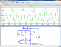
I have a little problem with LTspice, here
http://www.diyaudio.com/forums/tubes-valves/74903-survey-aikido-distortion-18.html#post4721887
http://www.diyaudio.com/forums/tube...er-ecc82-12au7-line-preamp-6.html#post4721929
In few words, in a simulation of an optimized SRPP, the distortion spectrum depends on coupling capacitor.
Thanks in advance.
You have DC drift in your circuit which is causing spectral leakage in the FFT. Using the Hann or Blackman windowing function selected from the FFT dialogue.
To use the .four function you will need to eliminate the source of drift or run some extra cycles to let it settle.
To use the .four function you will need to eliminate the source of drift or run some extra cycles to let it settle.
You have DC drift in your circuit which is causing spectral leakage in the FFT. Using the Hann or Blackman windowing function selected from the FFT dialogue.
To use the .four function you will need to eliminate the source of drift or run some extra cycles to let it settle.
OK, thank you very much!
With 190 extra cycles both results are a bit more closer, I will try 1990, but my old PC take ages to make a simulation.

another trick is the .savebias and .loadbias commands - you can run at coarse time step with zero input for long times to get settled values and save them, then use them to initialize your higher time res, shorter run time sims as long as your circuit changes don't change the offset or renumber the nodes
for really difficult convergence, usually very high dc loop gain circuits I sometimes have to resort to scattershot .nodeset statements to get any initial DC solution at all
for really difficult convergence, usually very high dc loop gain circuits I sometimes have to resort to scattershot .nodeset statements to get any initial DC solution at all
Usually using the Hann or Blackman window will reduce the leakage enough to see some harmonics. If it takes that many cycles to get rid of drift, there's probably something wrong with the simulation.
I have no idea about those windows.
I think that it is a very difficult case to simulate because the optimized SRPP has a null in distortion which depends on the load, and it is a critical load.
another trick is the .savebias and .loadbias commands - you can run at coarse time step with zero input for long times to get settled values and save them, then use them to initialize your higher time res, shorter run time sims as long as your circuit changes don't change the offset or renumber the nodes
for really difficult convergence, usually very high dc loop gain circuits I sometimes have to resort to scattershot .nodeset statements to get any initial DC solution at all
I will think a little about this, thanks a lot to both.
- Status
- This old topic is closed. If you want to reopen this topic, contact a moderator using the "Report Post" button.
- Home
- Design & Build
- Software Tools
- Things you should know about LTSpice