I'd like to start a thread on SPICE models and SPICE help. Some people tried to start on in the past, but this one is not gonna go under as I guarentee I have lots of SPICE related questions.
I'd like to start out by saying that for those that need models. Many manufactors supply them at their site. FOr tube models, The following 2 sites are good:
Norman Koren's Vacuum Tube audio page
Duncan's Amp pages
I'd like to say that for those looking for discontinued transistors,
Zetex is awesome. They have a massive SPICE library as well as putting the SPICE data in their PDF files. Nice.....
Well, I'll start off, here's my question....
I can't entice SPICE to play nice, with......hehe sorry. SPICE doesn't like it when I leave parts "dangling" so how does one take care of the input and output of a circuit.
For me it would be the input and output of Slone's MOSFET hybrid ie. Fig 11.14, p. 354 in High Power Audio Amplifier Construction Manual.
So what do you think?
Eternalightwithin

I'd like to start out by saying that for those that need models. Many manufactors supply them at their site. FOr tube models, The following 2 sites are good:
Norman Koren's Vacuum Tube audio page
Duncan's Amp pages
I'd like to say that for those looking for discontinued transistors,
Zetex is awesome. They have a massive SPICE library as well as putting the SPICE data in their PDF files. Nice.....
Well, I'll start off, here's my question....
I can't entice SPICE to play nice, with......hehe sorry.
 SPICE doesn't like it when I leave parts "dangling" so how does one take care of the input and output of a circuit.
For me it would be the input and output of Slone's MOSFET hybrid ie. Fig 11.14, p. 354 in High Power Audio Amplifier Construction Manual.
So what do you think?
Eternalightwithin
Good point, to start this thread but as you say, many of them died without much response.
Indeed when searching the net you'll find more spice library's than you will ever need.
Not sure what the reason could be, there was even someone who proposed to make a forum on spice models. Not much response on that.
I guess the problem is that there are many programs around, many people use different software, and only few people have the skills to work with them. (I don't consider myself as a skilled person in spice).
/Hugo
EternaLightWith said:........I can't entice SPICE to play nice, with......hehe sorry.SPICE doesn't like it when I leave parts "dangling" so how does one take care of the input and output of a circuit.
For me it would be the input and output of Slone's MOSFET hybrid ie. Fig 11.14, p. 354 in High Power Audio Amplifier Construction Manual.
So what do you think?
Eternalightwithin
I wanted a spice forum ages ago, but for some reson, that never happened.
Try loading with resistance of a silly value, 1 GigOhm or so..
Not sure I understand....
At one end of the circuit, the input, there is C1. SPICE says C1 is dangling. So it won't run. Same with the output, there is an inductor there that SPICE doesn't like dangling. Now granted I can put a load at the output, but that still leaves the problem of the input.
P.S. I there a way to inject a sine wave into the input? Or will it do that automatically when I run the simulations?
Eternalightwithin
How do I find out circuit distortion
I'm using bSpice to simulate a circuit. Trying to find out the distortion of said circuit. It won't run the simulator unless I put in an AC voltage source at the input. So I did that, yet the graph and tables either give me zeros for distion or a really small number like 1e-31
I'm wondering what I'm doing wrong?
Eternalightwithin
I'm using bSpice to simulate a circuit. Trying to find out the distortion of said circuit. It won't run the simulator unless I put in an AC voltage source at the input. So I did that, yet the graph and tables either give me zeros for distion or a really small number like 1e-31

I'm wondering what I'm doing wrong?
Eternalightwithin
Oh Really?
"Indeed when searching the net you'll find more spice library's than you will ever need."
HA HA HA HA HA HA HA HA HA HA HA HA HA HA HA HA HA HA HA HA
HA HA HA HA HA HA HA HA HA HA HA HA HA HA HA HA HA HA HA HA
HA HA HA HA HA HA HA HA HA HA HA HA HA HA HA HA HA HA HA HA
HA HA HA HA!
You are joking, aren't you ?
Why do so many people ask me for Spice models and tell me how bad some of the ones posted on the net are?
I think I hurt myself laughing. That was great. I have tears running down my face. You are extremely funny guy. Tell us another one please!
Attachments
Re: Oh Really?
Pretty please, Fred?
Couldn't find it on the net.
/Hugo
Would you please, pretty please give us a spice model for the IRF9610?Fred Dieckmann said:You are joking, aren't you ?
Pretty please, Fred?
Couldn't find it on the net.

/Hugo
I can't seem to make reasonable distortion graphs.
I'm trying to model circuits in bSPICE and I can't seem to get good cisuals out of the simulations.
Tried doing noise and distortion graphs and alll I get is crap, actually I don't get anything.
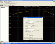
After a bit of fooling around I managed to get this graph simulating Self's Blameless amp. The file is attached. O got this by putting a DC source with an AC signal injected into is (1V) at the inputs and put a voltage meter at the speaker outputs.
I still can't make heads or tail or it. I need to have it look like it does in the textbooks. Easier to compare then.
So what does one put into the circuit to simulate these circuits and what parameters or equations are needed to get a good graph that makes sense?
Eternalightwithin
Attachments
- Status
- This old topic is closed. If you want to reopen this topic, contact a moderator using the "Report Post" button.
- Home
- Design & Build
- Software Tools
- 1- 800- Go- Spice

