looks great ") You might also want to check what the native sampling rates of your card are. That looks like you have 44.1Khz sampling, but most cards are native 48, 96, 192... you are best off running at a native rate, so might be better setting to 48Khz sampling rate.
You might also want to check what the native sampling rates of your card are. That looks like you have 44.1Khz sampling, but most cards are native 48, 96, 192... you are best off running at a native rate, so might be better setting to 48Khz sampling rate.
Tony.
You might also want to check what the native sampling rates of your card are. That looks like you have 44.1Khz sampling, but most cards are native 48, 96, 192... you are best off running at a native rate, so might be better setting to 48Khz sampling rate. Tony.
You're right. It is 48KHz sampling rate for this sound card. I'll change it immediately.
Fairground Attraction - Perfect - YouTube

Fairground Attraction - Perfect - YouTube
You're welcome! Glad you got it.
Just remember that the RCA outputs are about 4dB hotter than the max input level to the mic input. It's a common problem in audio, connecting a too hot line level into a mic input.
Last edited:
Hi folks.
I'd like to calibrate my system.
I have got an EMU 0404 USB. It measures pretty flat from analog-out to analog-in. I can't make use of it tough.
I'm using a full digital amp (DDX320) in the chain.
Measurement loop:
EMU-digital-out -> Toslink-> DDX320 -> ?? ->EMU-analog-in
What am I supposed to do?
I'd need to take the amp output as reference.
What's the best way to do that??
Thx
Calibration of your soundcard is straightforward--simply follow the prompts in Holm on the "device and Signal tab." This will generate a correction which is automatically applied to subsequent measurements to offset any sporty behaviour on the part of your computer audio..
I have measured the amplifier output by attaching a shielded cable to one of my channel (left or right) speaker cables and feeding the signal back into the microphone input of the Holm setup. This is pretty risky because everything is interconnected via the ground/shielding circuitry which means you could be applying far too much power. Proceed with very low gain settings and at least a small blocking cap or best of all an isolation transformer. What you should get is a typical Holm graph that shows the variations in gain thru your audio power system. I don't know of any way to introduce this as a true calibration signal into Holm's mysterious calculations but you can show it on every output graph as a reference against which to eyeball-gauge speaker responses.
I have measured the amplifier output by attaching a shielded cable to one of my channel (left or right) speaker cables and feeding the signal back into the microphone input of the Holm setup. This is pretty risky because everything is interconnected via the ground/shielding circuitry which means you could be applying far too much power. Proceed with very low gain settings and at least a small blocking cap or best of all an isolation transformer. What you should get is a typical Holm graph that shows the variations in gain thru your audio power system. I don't know of any way to introduce this as a true calibration signal into Holm's mysterious calculations but you can show it on every output graph as a reference against which to eyeball-gauge speaker responses.
I've done the standard - pretty straight forward - calibration - as I mentioned.
So. What your saying: Turn down the signal to 2VRMS (limit of input) on the amp output and loop it back in !?!?!?
Yes--you simply treat the amplifier output as though it was a microphone signal or a line-level input (I think your EMU 0404 soundcard has a line level input). Also reduce the amplifier output to a low value to avoid overdriving the computer. But you must be careful when you feed back to your computer from the speaker terminals because the shielding system connects all of your computer and audio equipment together on one side. Try to trace thru the circuitry from your amplifier ground to determine which side of the speaker cable is the ground side and connect that side to the shield side of the cable which runs to the computer microphone input. And insert a capacitor or, preferably, an isolation transformer in the circuit from speaker terminals back to sound card line (or microphone) input. Or you could do as I have done namely cross your fingers and go for it. But understand that you might damage your computer input circuitry.
This thread hasn't been active for awhile. So, I thought I'd 'wake it up' a bit with a question regarding interpretation of impulse response data.
I know there is much information in those first few squiggles at and beyond 0 ms. If a squiggle is up or down, then up and up or up and down, etc... You know what I'm getting at.
What does each mean?
Any help in prior posts in this thread or other threads someone could direct me to?
I know there is much information in those first few squiggles at and beyond 0 ms. If a squiggle is up or down, then up and up or up and down, etc... You know what I'm getting at.
What does each mean?
Any help in prior posts in this thread or other threads someone could direct me to?
BUMP! C'mon H.I. experts!
This thread hasn't been active for awhile. So, I thought I'd 'wake it up' a bit with a question regarding interpretation of impulse response data.
I know there is much information in those first few squiggles at and beyond 0 ms. If a squiggle is up or down, then up and up or up and down, etc... You know what I'm getting at.
What does each mean?
Any help in prior posts in this thread or other threads someone could direct me to?
Your the Doctor, let's see the "x-rays"...
Check out post #602. What does the impulse response tell you about the speaker being tested?
BUMP! C'mon H.I. experts!
The reason that we tend to not to use the impulse response directly is because it is very difficult to make interpretations. There is no real way to determine what each dip and peak means.
It is easy to state what an ideal impulse would look like and hence any deviation from this is less than ideal. The ideal impulse response of a loudspeaker is a doublet - a peak up followed by an equal size peak down. It can also be said that the longer the tail is the less desirable.
If a large perturbation occurs at some time after the doublet, then the delay time can often be useful in finding out where this errant signal is coming from.
Bottom line is that the impulse response is necessary for finding where to "window" the data, but past that it takes a lot of experience to see much more than that directly in the time domain.
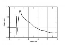
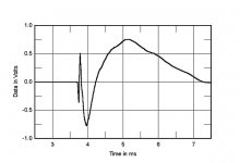
I'll stick my neck out and say the I.R. in post #602 shows a nice peak @ 0 seconds followed by an equal size dip (doublet Earl?), followed by another small peak (drivers in phase?).
My I.R. show a consistent blip at around 4 ms. That's my first reflection and I window below that of my FR's.
John Atkinson seems to have much to say about I.R.s when he does his measurements.
Here's a typical I.R. comment from J.A. (on the left):
"The RTi A3's step response on the tweeter axis (fig.7) shows that both drive-units are connected in positive acoustic polarity, and :implies that the best integration of the two will occur just below the tweeter axis."
Fig.7 Polk RTi A3, step response on HF axis at 50" (5ms time window, 30kHz bandwidth).
Here's another J.A. step response comment for a 3-way speaker (on the right).
"In the time domain, the SS-AR2's step response on the tweeter axis (fig.7) indicates that the tweeter and midrange units are connected in inverted acoustic polarity, the woofers in positive polarity, and that the tweeter's output arrives first, followed by the midrange's and then the woofers'. However, the fact that the decay of each unit's step blends smoothly into the start of the step of the next unit lower in frequency correlates with the excellent frequency-domain integration of their outputs seen in fig.3, and implies optimal crossover design."
Attachments
Last edited:
BUMP! C'mon H.I. experts!
I think the fewer the squiggles the better. Ideal is one up and minimal overshoot or ringing. It should look something like the logo for Holmimpulse.
Here is the response from my speaker:

Holmimpulse and JAVA update
Since I updated JAVA (now ver. 51) and am no longer able to use Holmimpulse. It gets through the initialization screens and then kicks me back to the windows systems (Windows 7). I reloaded Holmimpulse and the problem remains.
Is anyone else having this difficulty?
Since I updated JAVA (now ver. 51) and am no longer able to use Holmimpulse. It gets through the initialization screens and then kicks me back to the windows systems (Windows 7). I reloaded Holmimpulse and the problem remains.
Is anyone else having this difficulty?
I've had problems with win7 and corrupted save files/prefs files in Holm.
Have a look under c:\users\yourusername\AppData\Roaming\HOLM Acoustics\Holm Impulse
Make a backup of the files there (in case it isn't the problem, and also because the zip file has your most recent measurements in it) and then delete them all. Try starting holm up again and hopefully it should work.
It will have reset to defaults and your measurement files will be gone, These can potentially be retrieved by unzipping and re-importing individual measurements.
Hope that helps!
Tony.
- Home
- Design & Build
- Software Tools
- HOLMImpulse: Measurements in practice