Hi there,
I'm sorry if this sounds like a silly question.
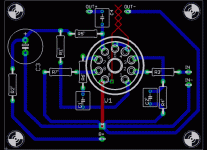
I'm trying to create my first PCB circuit with eagle.
I'm finding some difficulties in creating the board from the schematic.
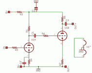
I just would like to know if you have some hints to create a board containing a single 12ax7 (2 triodes taking signal of the first triode from the anode via a decoupling cap and putting it in the 2nd grid and taking out the sig from the 2 anode).
The main difficulty is to create a single layer board without critical traces to cross each other (i.e. passing under a cap or a resistor) and to have on the same board heater supply (6.3 V don't want to use 12V) and the Anode supply ( elettrolitic cap plus resistor from main supply rail (distribute filtering).
I think this configuration is a sort of "stereotype" in building amp (guitar amp) so I would like to know if some "standard" solution exists or which traces I can cross without having problems (i.e. crosstalk or noise).
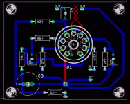
Which traces cannot "pass" one close to the other? I put a sample schematic in this post..this is the "basic" module I'd like to do..The tube socket is put on the bottom layer (and the tube pass through the chassis) (i used Valves.lbr)
which is the minimum width of traces to use B+ is 350V ? (1oz copper board, home made board with UV lamp)?
Thanks a lot if anyone can help.
Attachments
Thanks a lot!
some questions..
Is it possible to have the trace of the cathode Resistor R4 under the Resistor that feed the grid of the first tube? (no crosstalk/ noise on it?)
(the same happens for R6 2nd Grid).
Any advantage in using a Ground plane (i mean leaving copper between traces and use it as a ground?) dosen't it works as a shield?
Another thing..u didn't put traces for heaters..but wires...I'd like to have traces too for heaters on PCB ;-)
Thanks again for your work!
Krusty
Hi I would not be too worried about crosstalk at those current levels... I think max about 1.6mA on that tube... if it bothers you, use the resistor legs to create some distance from the board
You can route pin nine straight up, then a few mm 90 right, and out between pin 5 and 6.
Avoid ground planes when you are not looking for some of the side affects... I think they are especialy unwanted due to the many high impendance nodes...
You can route pin nine straight up, then a few mm 90 right, and out between pin 5 and 6.
Avoid ground planes when you are not looking for some of the side affects... I think they are especialy unwanted due to the many high impendance nodes...
I don't think your twisted traces are going to work. They are on the same layer, so are just a short circuit, and run into a pin, and they are too thin for the heater current. My experience is that you should either simply add some vias near the socket pins to allow for twisted wire to be connected, or move the socket toward the edge of the board to minimize trace length (and keep them close), or use DC, which is quite easy for a 12V tube. If you only have a 6.3V winding, use a voltage doubler and a regulator.
the red represents some wire... 
My current prototype uses the schematic with the 5V reg, the 2 diodes and the Transistor... seems pretty spot on 6.35V with no load, supposedly good up to 5A.
http://www.freewebs.com/valvewizard/heater.html

My current prototype uses the schematic with the 5V reg, the 2 diodes and the Transistor... seems pretty spot on 6.35V with no load, supposedly good up to 5A.
http://www.freewebs.com/valvewizard/heater.html
- Status
- This old topic is closed. If you want to reopen this topic, contact a moderator using the "Report Post" button.
- Home
- Design & Build
- Software Tools
- EAGLE PCB help with socket on it


