Here we go...
rename the attachment to opsup.sub and store it in the LTspice \lib\sub folder for easy access (no paths requiered)
- place a command .lib opsup.sub in your sim
- use the opamp2 symbol for your opamps and change the value field to opsup or opsupcl.
You may specifiy the usual Aol (default: 1e6) and Gbw (default: 50MegHz) parameters for both plus there are additional ones:
opsup:
- Iq (defines the quiescent current, default is 10mA)
opsupcl (cl stands for clamped -- clamps the output voltage to the supply levels)
- Iq (defines the quiescent current, default is 10mA)
- Rout (defines output resistance, default is 20R)
You can specify those by editing spiceline or spiceline2 in the attribute editor dialog (right-click on the opamp)
If you want to make those permanently visible then copy and edit the opamp2.asy symbol.
- Klaus
Attachments
jcx said:Hi John,
I believe I could implement Bob's "PIM" measurement in LtSpice
See this to measure TIM
Attachments
Rafael.luc said:
See this to measure TIM
i've been experimenting with a program called "Spectrum Lab" available as freeware here:
http://freenet-homepage.de/dl4yhf/spectra1.html
it has a DSP function block that you can create custom signals and filters with, and it seems like it would be simple to implement an IM analyzer with it.
Very large threat. But I miss by this intense discussion one thing: The verification how far the simulation results to real life measurements actually differ
If a member the measured values of his amp posted here, I could check by simulation of my software to see how far the simulated results differ (preferably simple circuit - at best a pure power amp device).
What do you like about this?
If a member the measured values of his amp posted here, I could check by simulation of my software to see how far the simulated results differ (preferably simple circuit - at best a pure power amp device).
What do you like about this?
Hi
I wonder if someone did simulation of IMD in LTspice?
http://www.diyaudio.com/forums/showthread.php?postid=1349571#post1349571
I'm trying to do, but I do not know if is correct(Attached)!
Thanks
I wonder if someone did simulation of IMD in LTspice?
http://www.diyaudio.com/forums/showthread.php?postid=1349571#post1349571
I'm trying to do, but I do not know if is correct(Attached)!
Thanks
Attachments
that looks about right. you may want to set your minimum timestep to about 1us or so and make sure you have data compression turned off. also, look up some of the standard tone pairs used for IMD measurements, as there are some like SMPTE using 60hz+7khz in a 4:1 ratio and measuring the sidebands of the 7khz tone, or ITU-R which uses 19khz+20khz in a 1:1 ratio and measuring any 1khz component that turns up. if you have heard test signals such as the two-tone test used as a warning signal in the Emergency Alert System in the US, it's usually 900hz+1khz in a 1:1 ratio, and any 100hz (and sometimes the 1900hz) component is measured. such a two-tone IMD test is primarily used for radio equipment with a limited audio bandwidth (2khz to 5khz).
Yes I'm doing it, and disabling the compression with the command:unclejed613 said:that looks about right. you may want to set your minimum timestep to about 1us or so and make sure you have data compression turned off. also
.options plotwinsize=0
unclejed613 said:look up some of the standard tone pairs used for IMD measurements, as there are some like SMPTE using 60hz+7khz in a 4:1 ratio and measuring the sidebands of the 7khz tone, or ITU-R which uses 19khz+20khz in a 1:1 ratio and measuring any 1khz component that turns up. if you have heard test signals such as the two-tone test used as a warning signal in the Emergency Alert System in the US, it's usually 900hz+1khz in a 1:1 ratio, and any 100hz (and sometimes the 1900hz) component is measured. such a two-tone IMD test is primarily used for radio equipment with a limited audio bandwidth (2khz to 5khz). [/B]
I read that in LTspice that is only as possible to measure in frequencies next.
this website is IMD measurements (Graf-6)
http://www.littlefishbicycles.com/poweramp/
I want to know is how to analyze the graphic, would be the amplitude of residual?
-seems that there is any way to get the value of IMD in %
your fft plot looks like you need to improve the "noise" floor
use max time step < (analysis length)/(fft bins)
use a window - I like Blackman - you do need >4x fft length to reslove the frequency components (more than 4 periods of the lowest frequency component)
use integer number of periods of both frequencies in .tran length or a really long record and good window
if you have turn-on settling issues you may need to allow some sim time before collecting data for the fft (tstart)
its possible to do very complex "analysis" with behavioral sources performing math on the waveform:
http://www.diyaudio.com/forums/showthread.php?postid=1333137#post1333137
the basic pattern could be used as a basis for a 2-tone signal analysis
the sidebands in the residual after subtracting the test tones could be rms summed for a % output
I've mentioned earlier that the IMD could also be separated into "AM" and "FM" components
In this case I have start a new threat:
http://www.diyaudio.com/forums/showthread.php?p=1914082#post1914082
perhaps one of you knows good brand names of such personal computer measure systems for transistor analysing and p-spice modelling
http://www.diyaudio.com/forums/showthread.php?p=1914082#post1914082
perhaps one of you knows good brand names of such personal computer measure systems for transistor analysing and p-spice modelling
Femm
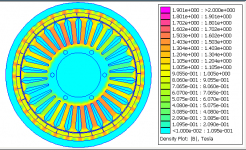
For those who's interest goes beyond spice and its various brands, I can recommend 'FEMM', written by David Meeker. As summarized in the manual:
"FEMM is a suite of programs for solving low frequency electromagnetic problems on two-dimensional planar and axisymmetric domains. The program currently addresses linear/nonlinear magneto-static problems, linear/nonlinear time harmonic magnetic problems, linear electrostatic problems, and steady-state heat flow problems."
Although I'm using it for designing something else than audio gear (i.e. a hub motor for my e-bike) I think it might be useful for simulating some audio components as well. Think of inductors, heat sinks, speaker magnets or maybe even a direct drive motor for turntables.
For more info see: Finite Element Method Magnetics: HomePage
Not unimportant, it's free! (some commercial programs cost over $10000)
Below a picture of the magnetic induction inside a BLDC motor designed for my e-bike.
Regards,
Edmond.
Attachments
in this case this thread could be of interest
http://www.diyaudio.com/forums/soli...ling-how-do-i-generate-p-spice-parameter.html
http://www.diyaudio.com/forums/soli...ling-how-do-i-generate-p-spice-parameter.html
Hi,
I have a question for you guys. Working on a simulation for the output end of an amp, running with 50v rails, I found the output transistors reaching high hfe at this voltage. (I was driving a 1r3 load) I was using Andy_c's mjl3281 models for the outputs. To back check these results, I ran the simulation from Andy_c's website with VCE set to 50v. At this setting the transistors showed hfe of about 228 at 10A.
Is this a believable number? Does hfe rise with voltage?
Thanks
Ken
Hi,
I have a question for you guys. Working on a simulation for the output end of an amp, running with 50v rails, I found the output transistors reaching high hfe at this voltage. (I was driving a 1r3 load) I was using Andy_c's mjl3281 models for the outputs. To back check these results, I ran the simulation from Andy_c's website with VCE set to 50v. At this setting the transistors showed hfe of about 228 at 10A.
Is this a believable number? Does hfe rise with voltage?
Thanks
Ken
Hi Ken,
The short answer is yes, hfe rises with voltage for a BJT. This is the Early effect. The higher reverse voltage across the base-collector junction increases the size of the depletion region, encroaching on the base and making it thinner. Thinner base usually increases hfe.
For your specific case, the number you are seeing for hfe seems high, especially at that current where you would expect some beta droop.
Some models have odd sensitivities to certain variables under certain conditions. Check with Andy_c on this. He can probably shed some light on it.
I don't have that model in front of me, but the first thing I would look at is the value of BF. BF is usually higher than peak beta of a transistor. However, if it is more than a factor of two higher than peak beta, I have sometimes discovered that the model has some undue sensitivities.
Cheers,
Bob
Bob,
During that discussion on bjt ft, I checked quite a few of the models I had
for ft and hfe versus freq/voltage. Most of the models appeared pretty
optimistic WRT hfe.
Once the VCE was increased the Hfe became -very- optimistic and beyond
what I have measured in most real devices. I didn't do a thorough model
versus reality check at various volatges but it was just an observation.
Needs further investigation.
cheers
Terry
- Home
- Design & Build
- Software Tools
- Spice simulation