I just went poking around the yahoo group. As I am already a member, that was easy, but I hadn't browsed through everything yet, which I just did, or mostly.
However I didn't find the exact one that I'm looking for, so I grabbed a few others, of a different type, and I will attempt to figure out how that works and if possible adapt something to suit the need.
If someone has such a model already made, I'm interested. I also think the TLP620 type would suit my needs, as I am looking for the dual leds for ac input. I need the models in the pdip4 type of case, not smd.
Some spice simulations are good and others aren't.
I did one for SMPS and it suggested primary current was 1.5 amps.
In reality offload it was virtually zero.
On the other hand a spice simulation showed parallel windings on a transformer with different inductances gives large currents.
A simulation of a soft limiter gave very close results to the final circuit.
I did an over current detect circuit that was nothing like the real world circuit. The real circuit was very noisy but the spice simulation had no noise !
I tried a simulation today that gave me an unexpected result. I'm not sure if this is a case of:
a) I have no idea what I am doing
b) The opamp is not suitable for the task
c) the model is way off
d) there is something going wrong in spice
e) something has possesed my computer and thinks it is funny to turn sine waves in to condoms.
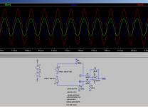
I'm trying to model a simple balanced to unbalanced converter. I bought some LM4562 Opamps which I blew up on the weekend due to stupidity, so perhaps option a) is the most likely. I then re-read the datasheet and found that they were limited to 0.7V input so were not suitable anyway and decided to try with the venerable opa2134.
Anyway circuit and output attached. 27% THD! and what a horrid waveform....
Fourier components of V(out)
DC component:0.298781
Harmonic Frequency Fourier Normalized Phase Normalized
Number [Hz] Component Component [degree] Phase [deg]
1 1.000e+03 1.928e+00 1.000e+00 -3.10° 0.00°
2 2.000e+03 3.736e-01 1.938e-01 86.42° 89.51°
3 3.000e+03 2.335e-01 1.211e-01 166.72° 169.82°
4 4.000e+03 1.600e-01 8.303e-02 61.49° 64.59°
5 5.000e+03 1.895e-01 9.834e-02 155.67° 158.77°
6 6.000e+03 5.690e-02 2.952e-02 -104.01° -100.92°
7 7.000e+03 6.503e-02 3.374e-02 141.63° 144.72°
8 8.000e+03 1.027e-01 5.329e-02 -133.73° -130.64°
9 9.000e+03 5.668e-02 2.941e-02 -40.75° -37.65°
Total Harmonic Distortion: 27.298151%
Any pointers as to what I have missed greatly appreciated
Tony.
a) I have no idea what I am doing
b) The opamp is not suitable for the task
c) the model is way off
d) there is something going wrong in spice
e) something has possesed my computer and thinks it is funny to turn sine waves in to condoms.
I'm trying to model a simple balanced to unbalanced converter. I bought some LM4562 Opamps which I blew up on the weekend
due to stupidity, so perhaps option a) is the most likely. I then re-read the datasheet and found that they were limited to 0.7V input so were not suitable anyway and decided to try with the venerable opa2134. Anyway circuit and output attached. 27% THD! and what a horrid waveform....
Fourier components of V(out)
DC component:0.298781
Harmonic Frequency Fourier Normalized Phase Normalized
Number [Hz] Component Component [degree] Phase [deg]
1 1.000e+03 1.928e+00 1.000e+00 -3.10° 0.00°
2 2.000e+03 3.736e-01 1.938e-01 86.42° 89.51°
3 3.000e+03 2.335e-01 1.211e-01 166.72° 169.82°
4 4.000e+03 1.600e-01 8.303e-02 61.49° 64.59°
5 5.000e+03 1.895e-01 9.834e-02 155.67° 158.77°
6 6.000e+03 5.690e-02 2.952e-02 -104.01° -100.92°
7 7.000e+03 6.503e-02 3.374e-02 141.63° 144.72°
8 8.000e+03 1.027e-01 5.329e-02 -133.73° -130.64°
9 9.000e+03 5.668e-02 2.941e-02 -40.75° -37.65°
Total Harmonic Distortion: 27.298151%
Any pointers as to what I have missed greatly appreciated
Tony.
Attachments
Hi ... well, looks like a strange output waveform ... I'm not an expert on this and are not familiar with all of the spice directives you use. But I notice that the supply voltages you use are not grounded in between the two supplies ...
Also, if you are not familiar with the spice directives you use a basic testing state could be to only include the .tran & .include opa134.sub directives. Also, instead of the .param for the resistors you might just make them plain resistors.
Are you sure your opa134 model is correct?
Maybe just using one voltage source at the input could help - connected on both sides of the voltage source to the non & inverting pins of the opamp ... ?
Those are my suggestions ... good luck with it ;-)
Jesper
Hi,
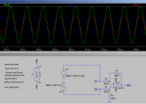
the prominent failures are the floating supplies.
Add a gnd-node between V1 and V2.
The resistors R6 and R7 are obsolete ... delete them.
I´ve seen the ptrantau command before, but couldn´t find its meaning at once.
What ís the second options command?
All else are correct commands.
Attached is a working sim.
To make my life easier, I´ve stored the complete command block with the supply and signal voltages as "sim basic params"-file.
So I can load the file, add the circuit and store the whole under a different name and have the most important sims right at hand.
The parameters for an FFT are automatically set.
You just need to define the parameter signal frequency (Freq) and signal voltage (Vin).
The DS of the LM4562 specs the Input Voltage Range on Page3 under Absolute Maximum Ratings to (V-)-0.7V and (V+)+0.7V and the Maximum Supply voltage Vs to 36V, with Vs=(V+)-(V-).
With symmetrical supply voltages this calculates to +-18.7V maximum input voltage.
jauu
Calvin
Attachments
Last edited:
Thank you calvin option a it was. an ID 10T error R6 and R7 were added in a desperate attempt to work out what was missing, I had a feeling it was a ground reference problem (I tried a ground resistor on the output as well) but it was the most basic of ground reference problems. DOH!
Jesper, the various extra directives are things that make getting clean fft's easier. I think the ptrantou was actually to disable one of the solvers that was causing issues with my synergy active crossover sim (I just copied the options accross).
I simply added the ground between the voltage sources and it works perfectly (at least in the sim)
Fourier components of V(out)
DC component:1.0119e-005
Harmonic Frequency Fourier Normalized Phase Normalized
Number [Hz] Component Component [degree] Phase [deg]
1 1.000e+03 2.000e+00 1.000e+00 -0.01° 0.00°
2 2.000e+03 2.223e-07 1.112e-07 177.97° 177.98°
3 3.000e+03 1.739e-09 8.696e-10 55.10° 55.11°
4 4.000e+03 3.780e-10 1.890e-10 -27.93° -27.92°
5 5.000e+03 3.913e-09 1.957e-09 45.39° 45.40°
6 6.000e+03 9.537e-10 4.769e-10 19.48° 19.49°
7 7.000e+03 3.915e-09 1.958e-09 -119.94° -119.93°
8 8.000e+03 2.044e-09 1.022e-09 -64.74° -64.73°
9 9.000e+03 5.955e-09 2.978e-09 22.91° 22.92°
Total Harmonic Distortion: 0.000011%
Thanks for the quick spotting of my mistake!!
Tony.
R6 and R7 were added in a desperate attempt to work out what was missing, I had a feeling it was a ground reference problem (I tried a ground resistor on the output as well) but it was the most basic of ground reference problems. DOH! Jesper, the various extra directives are things that make getting clean fft's easier. I think the ptrantou was actually to disable one of the solvers that was causing issues with my synergy active crossover sim (I just copied the options accross).
I simply added the ground between the voltage sources and it works perfectly (at least in the sim)
Fourier components of V(out)
DC component:1.0119e-005
Harmonic Frequency Fourier Normalized Phase Normalized
Number [Hz] Component Component [degree] Phase [deg]
1 1.000e+03 2.000e+00 1.000e+00 -0.01° 0.00°
2 2.000e+03 2.223e-07 1.112e-07 177.97° 177.98°
3 3.000e+03 1.739e-09 8.696e-10 55.10° 55.11°
4 4.000e+03 3.780e-10 1.890e-10 -27.93° -27.92°
5 5.000e+03 3.913e-09 1.957e-09 45.39° 45.40°
6 6.000e+03 9.537e-10 4.769e-10 19.48° 19.49°
7 7.000e+03 3.915e-09 1.958e-09 -119.94° -119.93°
8 8.000e+03 2.044e-09 1.022e-09 -64.74° -64.73°
9 9.000e+03 5.955e-09 2.978e-09 22.91° 22.92°
Total Harmonic Distortion: 0.000011%
Thanks for the quick spotting of my mistake!!
Tony.
Attachments
Yes I'm not expecting that in real life the noise floor, or the distortion will be anywhere near that low. I would like to achieve a noise floor of -120db and distortion of .0001%. The specs on the opa2134 are 0.00008% HD
I'm not sure about the noise figures though. In the spice sim with 10K resistors I get around 31nV/Hz1/2 but I don't know how to convert that to a db value (or whether it is even valid since it only let me put in one of the two inputs).
The application is to go between the balanced out of my Focusrite Scarlet 2i2 sound card and any unbalanced device I want to test. The 2i2's performance is poor when you connect the balanced out to a single ended device.
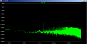
The sim could be optimized some more, I haven't done any tricky stuff like taking into account the period in the fourier statement. This was a quick and dirty one. I DID re-run the sim for the fft above, though changing to 0.6 seconds run time, saving from 0.4 seconds on. new .tran 0 0.6s 0.4s 1u
I normally use a 0.1u step for really fine ffts but it takes a long time to calculate.
I just ran it again with my "normal" long simulation command. .tran 0 220m 120m 0.1u part of the reason for all the grass in the above plot is the long time window for the fft (200ms)
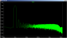
Below is the result from the 0.1uS step 220ms run (saving from 120ms on), but only specifying 90-100ms in the fft and blackman windowing. It gives a much clearer view of what is happening with the harmonics. The fundamental is at +4db and the 2nd harmonic is at -135db so it is pretty much all 2nd harmonic that is giving the fft result of 0.000011%
Tony.
I'm not sure about the noise figures though. In the spice sim with 10K resistors I get around 31nV/Hz1/2 but I don't know how to convert that to a db value (or whether it is even valid since it only let me put in one of the two inputs).
The application is to go between the balanced out of my Focusrite Scarlet 2i2 sound card and any unbalanced device I want to test. The 2i2's performance is poor when you connect the balanced out to a single ended device.
The sim could be optimized some more, I haven't done any tricky stuff like taking into account the period in the fourier statement. This was a quick and dirty one. I DID re-run the sim for the fft above, though changing to 0.6 seconds run time, saving from 0.4 seconds on. new .tran 0 0.6s 0.4s 1u
I normally use a 0.1u step for really fine ffts but it takes a long time to calculate.
I just ran it again with my "normal" long simulation command. .tran 0 220m 120m 0.1u part of the reason for all the grass in the above plot is the long time window for the fft (200ms)
Below is the result from the 0.1uS step 220ms run (saving from 120ms on), but only specifying 90-100ms in the fft and blackman windowing. It gives a much clearer view of what is happening with the harmonics. The fundamental is at +4db and the 2nd harmonic is at -135db so it is pretty much all 2nd harmonic that is giving the fft result of 0.000011%
Tony.
Attachments
Last edited:
Neither the LME49720 nor the OPA2134 will get you to the distortion level you seek. They both quite good but the diff amp with them shows a distinctive preference for the inverting input. The best seems to be the AD797 and the LME49990 seems to work in my experiments so far. There may be others. If -100 dB is OK any of them will be fine.
The sims are interesting but really won't show all the issues at the below -100 dB range. I doubt they are audible issues in any case.
The sims are interesting but really won't show all the issues at the below -100 dB range. I doubt they are audible issues in any case.
Thanks 1Audio, I've got some opa2134's so I can bread board it and see just how far it is out. If I were using it in my preamp (which I may well do now) then -100db would be fine. When trying to use it for test gear (specifically for testing distortion and noise performance of other circuits) then I need to try and get it as far out of the picture as I can, so better opamps are on the cards.
Thanks for the heads up on the AD797 and LME49990!
Tony.
Thanks for the heads up on the AD797 and LME49990!
Tony.
i used pspice to simulate car battery charger i make almost half year ago and it charged well every battery from small gel 7,2ah to 120ah truck battery, i was boring today and as i have no real life scope i try to make simulation in pspice and results are horrible(?) , now i am starting to suspect i missed something in actual charger and my first bet would be more capacitance before regulator what get me realy nice dc no ripple not like that picture here ,are this programs real accurate?
in attach pics and pspice model thank you for help
in attach pics and pspice model thank you for help
Attachments
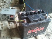
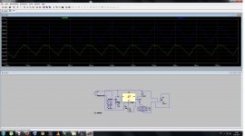
470uF is not enough for a very high output current, so for sure the ripple will be too large if your battery draws a lot of current.
thank you on fast answer, now when i look inside charger again i switched c1 and c2 when making it , and now when switched it back it wont work well there is more ripple on output , are this generic diodes in pspice ok ? and how can i edit them i have datasheet and .txt model of ones i am using?
The battery will charge fine with ripple on the supply. There are some techniques (probably discredited) for pulse charging batteries to get more power into them. The circuit is essentially a resistor limited charging circuit. It doesn't have any sophistication in limiting the current when the battery reaches full charge etc.
Most commercial chargers have just enough cap to function (more costs more. . .)
Most commercial chargers have just enough cap to function (more costs more. . .)
The battery will charge fine with ripple on the supply. There are some techniques (probably discredited) for pulse charging batteries to get more power into them. The circuit is essentially a resistor limited charging circuit. It doesn't have any sophistication in limiting the current when the battery reaches full charge etc.
Most commercial chargers have just enough cap to function (more costs more. . .)
yes i know battery will charge with ripple becouse i had normal store bought (cheap)battery charger with no actual caps after diodes,but lead acid battery would bubble too much..and thats why i make regulated, but if pspice simulations are correct this charger only has ripple on 7,5amps current but when on around 2 it is better..and there just slight bubbling when battery would be almost charged and i wanted to eliminate that also,it should be better to put less current to battery but for more time
does anyone know how to model a spice model (txt) to pspice?
Actually a properly charging lead acid battery (Not SLA) will offgass when its charging. Its perfectly normal. Read this: Trojan Battery Company Especially near the end. There is not a lot of current knowledge on lead acid since the focus is on newer technologies. However they have been in heavy use for at least 100+ years without a lot of change. SLA's, LI, NIMH and NICD all have different and complex requirements and are getting more focus.
The gasses from a battery (any type) is somewhat corrosive and in some cases combustible. make sure you have good ventilation.
The gasses from a battery (any type) is somewhat corrosive and in some cases combustible. make sure you have good ventilation.
Toni, you can copy the .model statement of a diode:
.model D (etc etc)
Then click on the ".op" button in the toolbar, paste it into the textbox, click okay and then click on your schematic to place the text there. Then edit the diode name to be the same as the name in the model.
.model D (etc etc)
Then click on the ".op" button in the toolbar, paste it into the textbox, click okay and then click on your schematic to place the text there. Then edit the diode name to be the same as the name in the model.
- Home
- Design & Build
- Software Tools
- Spice simulation