Well, I got my computer rebuilt, OS and all apps reinstalled, yada yada yada ") . I now have all the parameters for the proposed 2SK1530 subcircuit model extracted, including capacitances.
. I now have all the parameters for the proposed 2SK1530 subcircuit model extracted, including capacitances.
Just to recap, I've played games with the EKV model parameters to give the non-physical result that its internal capacitances are negligible. This means the capacitances will be dominated by the elements external to the MOSFET model inside the subcircuit. My plan for modeling the capacitances is as follows:
Cgs: Use an external fixed value
Cds: Determined by the capacitance parameters of the external body diode
Cgd: Use the same capacitance behavior that LTSpice uses in their VDMOS model. The formulas for Cgd can be found on page 141 of the LTSpice manual in PDF format. The formulas are as follows:
(1) Cgd = C * atan(a * Vgd) + D, for Vgd <= 0
(2) Cgd = A * tanh(a * Vgd) + B, for Vgd > 0
By equating the capacitances at Vgd = 0, the result is D = B. Likewise, by equating the first derivatives of the capacitances at Vgd = 0, the result is A = C. But the actual parameters are "a", "Cgdmax" and "Cgdmin". Using the results tanh(infinity) = 1 and atan(-infinity) = -pi/2 and some algebra, the result is:
A = C = (Cgdmax - Cgdmin) / (1 + pi / 2)
B = D = (Cgdmin + pi / 2 * Cgdmax) / (1 + pi / 2)
So I want to model this behavior as an external nonlinear capacitor. I'd like to provide an LTSpice model and a Micro-Cap model, as these seem to be the most commonly used free simulators. Both LTSpice and Micro-Cap allow a capacitor to be specified by its nonlinear charge characteristic Q(v). I know how to do this with LTSpice, but I could use some help with Micro-Cap. On page 416 of the Micro-Cap PDF reference manual, they give some guidelines for the charge attribute of a capacitor, but don't explicitly say what the netlist syntax looks like. Edmond, could you help me out with this by trying a standalone nonlinear capacitor using the charge attribute in Micro-Cap?
There needs to be some capability to use an "if" statement in the charge expression also. LTSpice allows this with its "if(expression, trueval, falseval)" syntax. I'd expect Micro-Cap to support this as well, but I'm not sure.
Anyway, it's necessary to find the charge expressions corresponding to equations (1) and (2) above using a table of integrals. For equation (1), the corresponding charge expression is:
Q(v) = A * (Vgd * atan(a * Vgd) - 1 / 2a * ln(1 + (a * Vgd)^2)) + B * Vgd
And for equation (2) the corresponding Q(v) is:
Q(v) = A / a * ln(cosh(a * Vgd)) + B * Vgd
So by combining these two expressions with an "if" statement, it looks doable. I'll try to get the LTSpice subcircuit working later today and hopefully post it tonight.
. I now have all the parameters for the proposed 2SK1530 subcircuit model extracted, including capacitances.Just to recap, I've played games with the EKV model parameters to give the non-physical result that its internal capacitances are negligible. This means the capacitances will be dominated by the elements external to the MOSFET model inside the subcircuit. My plan for modeling the capacitances is as follows:
Cgs: Use an external fixed value
Cds: Determined by the capacitance parameters of the external body diode
Cgd: Use the same capacitance behavior that LTSpice uses in their VDMOS model. The formulas for Cgd can be found on page 141 of the LTSpice manual in PDF format. The formulas are as follows:
(1) Cgd = C * atan(a * Vgd) + D, for Vgd <= 0
(2) Cgd = A * tanh(a * Vgd) + B, for Vgd > 0
By equating the capacitances at Vgd = 0, the result is D = B. Likewise, by equating the first derivatives of the capacitances at Vgd = 0, the result is A = C. But the actual parameters are "a", "Cgdmax" and "Cgdmin". Using the results tanh(infinity) = 1 and atan(-infinity) = -pi/2 and some algebra, the result is:
A = C = (Cgdmax - Cgdmin) / (1 + pi / 2)
B = D = (Cgdmin + pi / 2 * Cgdmax) / (1 + pi / 2)
So I want to model this behavior as an external nonlinear capacitor. I'd like to provide an LTSpice model and a Micro-Cap model, as these seem to be the most commonly used free simulators. Both LTSpice and Micro-Cap allow a capacitor to be specified by its nonlinear charge characteristic Q(v). I know how to do this with LTSpice, but I could use some help with Micro-Cap. On page 416 of the Micro-Cap PDF reference manual, they give some guidelines for the charge attribute of a capacitor, but don't explicitly say what the netlist syntax looks like. Edmond, could you help me out with this by trying a standalone nonlinear capacitor using the charge attribute in Micro-Cap?
There needs to be some capability to use an "if" statement in the charge expression also. LTSpice allows this with its "if(expression, trueval, falseval)" syntax. I'd expect Micro-Cap to support this as well, but I'm not sure.
Anyway, it's necessary to find the charge expressions corresponding to equations (1) and (2) above using a table of integrals. For equation (1), the corresponding charge expression is:
Q(v) = A * (Vgd * atan(a * Vgd) - 1 / 2a * ln(1 + (a * Vgd)^2)) + B * Vgd
And for equation (2) the corresponding Q(v) is:
Q(v) = A / a * ln(cosh(a * Vgd)) + B * Vgd
So by combining these two expressions with an "if" statement, it looks doable. I'll try to get the LTSpice subcircuit working later today and hopefully post it tonight.
andy_c said:...........
So I want to model this behavior as an external nonlinear capacitor. I'd like to provide an LTSpice model and a Micro-Cap model, as these seem to be the most commonly used free simulators. Both LTSpice and Micro-Cap allow a capacitor to be specified by its nonlinear charge characteristic Q(v). I know how to do this with LTSpice, but I could use some help with Micro-Cap. On page 416 of the Micro-Cap PDF reference manual, they give some guidelines for the charge attribute of a capacitor, but don't explicitly say what the netlist syntax looks like. Edmond, could you help me out with this by trying a standalone nonlinear capacitor using the charge attribute in Micro-Cap?
There needs to be some capability to use an "if" statement in the charge expression also. LTSpice allows this with its "if(expression, trueval, falseval)" syntax. I'd expect Micro-Cap to support this as well, but I'm not sure.
................
Hi Andy,
I'm glad you are on the air again and you did nice work in the mean time.
As for the "if" statement, this also can be used in Micro-Cap, as 'help' says: " IF(b,z1,z2) If b is true, the function returns z1, otherwise it returns z2" Please allow me some time to figure it out, as I'm also busy with some other projects too (the ultimate amp and EC).
Please go on, you're really doing a good job. Till soon.
Cheers, Edmond.
Here is the LTSpice subcircuit model for the 2SK1530. I've attached two LTSpice test circuits, one for the DC parameters and another for the capacitances. The spreadsheet used for all parameter fitting is also attached. The spreadsheet has more worksheet tabs than it looks like at first, so use the tab scroll controls at the lower left of the Excel window to navigate them.
In the spreadsheet, you'll see graphs of measured and simulated Id vs. Vgs, Cds vs. Vds, body diode Id vs. Vd, Cgd vs. Vgs and some other data. To get the spreadsheet to run, you'll need to go to Tools, Macro, security and set the security to "medium". This will allow you to accept or reject macro usage on a per-file basis. The EKV function is included - just press Alt-F11 to see the VBA code. One VBA module (Module1) has the EKV function. The second module requires a bit of explanation.
When fitting the body diode capacitance, the measured Cds value is needed, which means subtracting Crss from Coss. But when the Engauge Digitizer software is used to capture the Coss and Crss curves, the x values captured (Vds) are in general different for the two curves. So I wrote a simple linear search function with linear interpolation that calculates a new Crss vs Vds curve, with the Vds values from the Coss vs. Vds curve. Then the curves can be subtracted. This is done with the interp_lookup() function in Module2.
There is no body diode DC data on the 2SK1530 datasheet, so I captured the data from the IRFP240 and used that. I don't think this is too important, as this diode is, of course, normally off. You can see in the Excel graphs that the simulated body diode capacitance matches the datasheet Cds very closely.
In the subcircuit text file, you can see the usage of the "if" statement with a charge function to specify the nonlinear Cgd. The variable "x" in that expression is an LTSpice-specific variable meaning "the voltage across the capacitor" (pin 1 minus pin 2). So "x" corresponds to Vgd. I also added a 0.383 Ohm drain resistor to better fit the datasheet data in the triode region. It's easier to include it and set it to a near-zero value if one decides it's not appropriate than to add it later if it's decided that it's necessary.
Now that I've got the techniques down, along with a working spreadsheet, it should be much easier and quicker to do parameter extraction for other devices. Next will be the 2SJ201, then the IRFP240 and FQA12P20 (IRFP9240 substitute).
Attachments
EKV
Hi Andy.
And here is the EKV model for MC8.
As MC8 has some trouble with nonlinear expressions for capacitors, it might be necessary to increase the global parameter RELTOL from 1m to 30m or so, dependent on the time step size in the transient analysis.
Cheers, Edmond.
.SUBCKT 2SK1530EKV 1 2 3
* Node 1 -> Drain
* Node 2 -> Gate
* Node 3 -> Source
***************************************
+PARAMS: Cgdmin = 42.8114p
+PARAMS: Cgdmax = 1216.887p
+PARAMS: a = 0.31548599
+PARAMS: B = { ( Cgdmin + 0.5 * pi * Cgdmax ) / ( 1 + 0.5 * pi ) }
+PARAMS: C = { ( Cgdmax - Cgdmin) / ( 1 + 0.5 * pi ) }
M1 4 5 3 3 NMOS44
RG 2 5 1m
RD 1 4 1m
DDS 3 1 DDS
CGS 5 3 850p
CGD 2 1 { if( V(2,1) > 0, a * tanh( a * V(2,1) ) + B, C * atan( a * V(2,1) ) + B ) }
.MODEL NMOS44 NMOS (LEVEL=44 L=2U W=0.5m
;+ EKVINT = 1
+ cox = 7e-4
+ xj = 1e-8
+ vto=1.97 gamma=5.9999694 phi=3.4298218
+ kp=7.95e-2
+ e0=2.0568449051e+11
+ ucrit=2.6680517254825e+13
+ dl=0 dw=0
+ lambda=1.1305e5
+ ibn=1.0 iba=0 ibb=3.0e8
+ weta=0.0 q0=0 LK=2.9e-7
+ leta=0.0 rsh=0.0
+ )
******************************************
.MODEL DDS D (CJO= 630p VJ=0.9 M=.55
+RS=0.005 IS=1E-10 TT=20.5n N=1.12 BV=200)
*****************************************
.ENDS
andy_c said:Here is the LTSpice subcircuit model for the 2SK1530. I've attached two LTSpice test circuits, one for the DC parameters and another for the capacitances. The spreadsheet used for all parameter fitting is also attached. The spreadsheet has more worksheet tabs than it looks like at first, so use the tab scroll controls at the lower left of the Excel window to navigate them.
In the spreadsheet, you'll see graphs of measured and simulated Id vs. Vgs, Cds vs. Vds, body diode Id vs. Vd, Cgd vs. Vgs and some other data. To get the spreadsheet to run, you'll need to go to Tools, Macro, security and set the security to "medium". This will allow you to accept or reject macro usage on a per-file basis. The EKV function is included - just press Alt-F11 to see the VBA code. One VBA module (Module1) has the EKV function. The second module requires a bit of explanation.
When fitting the body diode capacitance, the measured Cds value is needed, which means subtracting Crss from Coss. But when the Engauge Digitizer software is used to capture the Coss and Crss curves, the x values captured (Vds) are in general different for the two curves. So I wrote a simple linear search function with linear interpolation that calculates a new Crss vs Vds curve, with the Vds values from the Coss vs. Vds curve. Then the curves can be subtracted. This is done with the interp_lookup() function in Module2.
There is no body diode DC data on the 2SK1530 datasheet, so I captured the data from the IRFP240 and used that. I don't think this is too important, as this diode is, of course, normally off. You can see in the Excel graphs that the simulated body diode capacitance matches the datasheet Cds very closely.
In the subcircuit text file, you can see the usage of the "if" statement with a charge function to specify the nonlinear Cgd. The variable "x" in that expression is an LTSpice-specific variable meaning "the voltage across the capacitor" (pin 1 minus pin 2). So "x" corresponds to Vgd. I also added a 0.383 Ohm drain resistor to better fit the datasheet data in the triode region. It's easier to include it and set it to a near-zero value if one decides it's not appropriate than to add it later if it's decided that it's necessary.
Now that I've got the techniques down, along with a working spreadsheet, it should be much easier and quicker to do parameter extraction for other devices. Next will be the 2SJ201, then the IRFP240 and FQA12P20 (IRFP9240 substitute).
Hi Andy,
Keep up the good work! We owe you a debt of gratitude. I'm looking forward to being able to do some MOSFET distortion sims with some confidence.
Thanks!
Bob
Bob Cordell said:Keep up the good work! We owe you a debt of gratitude. I'm looking forward to being able to do some MOSFET distortion sims with some confidence.
Thanks for your kind words Bob!
Edmond Stuart said:And here is the EKV model for MC8.
Hi Edmond,
The expression for Cgd that you have, shown below as:
CGD 2 1 { if( V(2,1) > 0, a * tanh( a * V(2,1) ) + B, C * atan( a * V(2,1)) + B ) }
needs to be changed to:
CGD 2 1 { if( V(2,1) > 0, C * tanh( a * V(2,1) ) + B, C * atan( a * V(2,1)) + B ) }
Since d/dx{tanh(x)} = 1 at x = 0, and also d/dx{atan(x)} = 1 at x = 0, these two functions should have the same multiplying constant in front of them so the derivatives of C(v) vs. v are continuous at v=0 for the two expressions. This won't matter if Vdg >= 0, but will give incorrect capacitance for Vdg < 0.
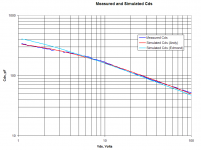
Also, I noticed you are using different body diode capacitance parameters than what I got from a best fit using the solver. I like the idea of modeling breakdown using the BV of the diode as you have done. How did you get TT though? I've attached a plot showing the measured Cds (= Coss - Crss) and the simulated Cds using the parameters I extracted and your parameters. Both are close.
Attachments
andy_c said:Hi Edmond,
The expression for Cgd that you have, shown below as:
CGD 2 1 { if( V(2,1) > 0, a * tanh( a * V(2,1) ) + B, C * atan( a * V(2,1)) + B ) }
needs to be changed to:
CGD 2 1 { if( V(2,1) > 0, C * tanh( a * V(2,1) ) + B, C * atan( a * V(2,1)) + B ) }
...................................
Also, I noticed you are using different body diode capacitance parameters than what I got from a best fit using the solver. I like the idea of modeling breakdown using the BV of the diode as you have done. How did you get TT though? I've attached a plot showing the measured Cds (= Coss - Crss) and the simulated Cds using the parameters I extracted and your parameters. Both are close.
Hi Andy,
You're quite right regarding CGD. ii's C*tanh. Apperently. I got trapped in one of your previous equations, where it says: A*tanh.
Regarding the diode, again you're right. I just forgot to replace my old model by yours, which indeed is better. Thanks for the plot.
>How did you get TT though?
I don't know exactly, it is five years ago I made this model. Probably, I just copied the diode from model of a comparable MOSFET from NEC.
As for CGD, we are still not done, as the expression returns a value two times as high in MC9 AC analysis as in MC8. Happily the guys at Micro-Cap were so kind to figure out why and they found a solution that works in MC8 and MC9 as well. Their answer:
"Rather than using the capacitor, I would recommend using a current source to simulate the capacitance. Try the following to replace CGD.
GGD 2 1 VALUE={ if( V(2,1) > 0, C * tanh( a * V(2,1) ) + B, C * atan( a * V(2,1) ) + B ) * DDT(V(2,1)) } "
Here is the updated version and let's hope the last one.
Also notice that there's no need any longer to set RELTOL to a higher value.
.SUBCKT 2SK1530-EKV 1 2 3
* Node 1 -> Drain
* Node 2 -> Gate
* Node 3 -> Source
***************************
+PARAMS: Cgdmin = 42.8114p
+PARAMS: Cgdmax = 1216.887p
+PARAMS: a = 0.31548599
+PARAMS: B = { ( Cgdmin + 0.5 * pi * Cgdmax ) / ( 1 + 0.5 * pi ) }
+PARAMS: C = { ( Cgdmax - Cgdmin) / ( 1 + 0.5 * pi ) }
M1 4 5 3 3 NMOS44
RG 2 5 1m
RD 1 4 383m
DDS 3 1 DDS
CGS 5 3 850p
GGD 2 1 VALUE={ if( V(2,1) > 0, C * tanh( a * V(2,1) ) + B, C * atan( a * V(2,1) ) + B ) * DDT(V(2,1)) }
; Courtesy of Micro-Cap
.MODEL NMOS44 NMOS (LEVEL=44 L=2U W=0.5m
;+ EKVINT = 1
+ cox = 7e-4
+ xj = 1e-8
+ vto=1.97 gamma=5.9999694 phi=3.4298218
+ kp=7.95e-2
+ e0=2.0568449051e+11
+ ucrit=2.6680517254825e+13
+ dl=0 dw = 0
+ lambda=1.1305e5
+ ibn=1.0 iba=0 ibb=3.0e8
+ weta=0.0 q0=0 LK=2.9e-7
+ leta=0.0 rsh=0.0 )
****************************************************************************
.MODEL DDS D ( N=1.5517725590608 IS=2e-8 RS=0.009989 CJO=405.936p M=0.560182 VJ=2.403248 )
****************************************************************************
.ENDS
Cheers, Edmond.
Edmond Stuart said:As for CGD, we are still not done, as the expression returns a value two times as high in MC9 AC analysis as in MC8. Happily the guys at Micro-Cap were so kind to figure out why and they found a solution that works in MC8 and MC9 as well. Their answer:
"Rather than using the capacitor, I would recommend using a current source to simulate the capacitance. Try the following to replace CGD.
GGD 2 1 VALUE={ if( V(2,1) > 0, C * tanh( a * V(2,1) ) + B, C * atan( a * V(2,1) ) + B ) * DDT(V(2,1)) } "
That's great news! Thanks for your efforts with converting the model for Micro-Cap.
It seems that the Micro-Cap support is really good too.
I guess it's on to the 2SJ201 then
.Perhaps you knew this already, but: If you're using Pspice to simulate THD, pay attention to the simulating time and also to simulation step length. I have used such a simulating time that I get 10 periods of the signal, and step size of about 1/1000 of the period. Using too short simulating time and/or too large step will give wrong answers (at least I have been told so).
For a 1 kHz sine that means total simulating time 10 ms and step size 1 us.
But I have never used a spectrum analyzer to verify my simulations, so I cannot tell how exact values Pspice gives.
For a 1 kHz sine that means total simulating time 10 ms and step size 1 us.
But I have never used a spectrum analyzer to verify my simulations, so I cannot tell how exact values Pspice gives.
Re: Distortion measurement and SPICE
Not sure about PSPICE, but LTSpice requires some manual tweaking to get good distortion results. You'll need to use a SPICE directive ".OPTIONS plotwinsize=0" to disable waveform compression. The LTSpice default of doing an FFT of the entire waveform is not appropriate for distortion analysis. Try simulating, say, 10-16 cycles of the waveform, doing an FFT on the last 4-6 cycles. This allows the transient at the beginning to settle out. Take the time span of the FFT and divide it by the (number of FFT points - 1) and specify this as the maximum time step in transient.
Also, using the ".FOUR" directive in LTSpice is convenient. It automatically takes the FFT of the last cycle. In this case, use as a time step the time for one cycle divided by (FFT_point_count - 1). To see the results of the .FOUR analysis, do a "View, SPICE error log".
Finally, there is a sticky thread for SPICE simulation issues. Feel free to ask SPICE questions there also. There is currently some specialized model development discussion going on in that thread, but it's meant for all SPICE discussion. I don't want to be seen as "hogging" that thread.
teodorom said:I compared the results I can get, using the same models, with two different packages: PSPICE and LTSpice.
Even if I get absolutely the same results about idle currents, bias voltages, amplitudes, ..., I get very different results when I analyze the distortion on the output (by the Fourier analysis).
Not sure about PSPICE, but LTSpice requires some manual tweaking to get good distortion results. You'll need to use a SPICE directive ".OPTIONS plotwinsize=0" to disable waveform compression. The LTSpice default of doing an FFT of the entire waveform is not appropriate for distortion analysis. Try simulating, say, 10-16 cycles of the waveform, doing an FFT on the last 4-6 cycles. This allows the transient at the beginning to settle out. Take the time span of the FFT and divide it by the (number of FFT points - 1) and specify this as the maximum time step in transient.
Also, using the ".FOUR" directive in LTSpice is convenient. It automatically takes the FFT of the last cycle. In this case, use as a time step the time for one cycle divided by (FFT_point_count - 1). To see the results of the .FOUR analysis, do a "View, SPICE error log".
Finally, there is a sticky thread for SPICE simulation issues. Feel free to ask SPICE questions there also. There is currently some specialized model development discussion going on in that thread, but it's meant for all SPICE discussion. I don't want to be seen as "hogging" that thread
.PMA said:(the models make difference)
Very important, PMA. In fact, one can get quite astonishing differences in the same mosfet output stage (for example), at the same DC conditions, with standard "pwrmos" models instead of IR models. Latter do distort more
Good point, Andy !
Thanks.
I had already made a simulation of the circuit
 .
.
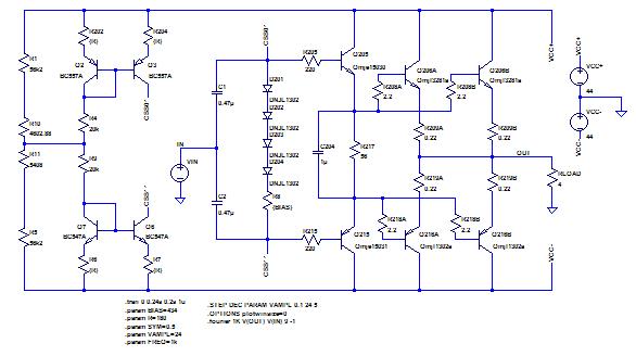
I had first used (in LTSpice) the directive
.tran 0 0.24s 0.2s 1u
You can see that I had already disgregarded the first milliseconds that the circuit takes to settle down.
I "measured" the distortion of bot input and output:
.fourier 1K V(OUT) V(IN) 9 -1
and I realized that even the distortion of the input was unacceptable. So I repeteated the simutation with 0.01us timestep. It took a whole night. The result, taken from the log file, is
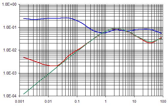
In green there is the 0.01us results, in red the 1us results.
Now, with the ".OPTIONS plotwinsize=0", even with a timestep of 1us I get exactly the same results in a very short time.
In blue there are the PSPICE results. 1us timestep, one night of simulations and the result is very different.
The NJL models are the ones you proposed.
I don't contribute to the other SPICE forum because I'm interested in mathematics and physics, not in religion.
Thanks again.
Thanks.
I had already made a simulation of the circuit
I had first used (in LTSpice) the directive
.tran 0 0.24s 0.2s 1u
You can see that I had already disgregarded the first milliseconds that the circuit takes to settle down.
I "measured" the distortion of bot input and output:
.fourier 1K V(OUT) V(IN) 9 -1
and I realized that even the distortion of the input was unacceptable. So I repeteated the simutation with 0.01us timestep. It took a whole night. The result, taken from the log file, is
In green there is the 0.01us results, in red the 1us results.
Now, with the ".OPTIONS plotwinsize=0", even with a timestep of 1us I get exactly the same results in a very short time.
In blue there are the PSPICE results. 1us timestep, one night of simulations and the result is very different.
The NJL models are the ones you proposed.
I don't contribute to the other SPICE forum because I'm interested in mathematics and physics, not in religion.
Thanks again.
Re: Good point, Andy !
Oh, if you mean the SPICE thread that starts here, you may be getting a bad impression by looking at the beginning of it. If you start reading it a few pages from the end, you'll see that it's now morphed into a problem-solving thread. I share your view of being interested in mathematics and physics as well.
teodorom said:I don't contribute to the other SPICE forum because I'm interested in mathematics and physics, not in religion.
Oh, if you mean the SPICE thread that starts here, you may be getting a bad impression by looking at the beginning of it. If you start reading it a few pages from the end, you'll see that it's now morphed into a problem-solving thread. I share your view of being interested in mathematics and physics as well.
I have spent some more time on that SPICE thread, so even if it start discussing about "religion", at the end it becomes a little bit more operational.
Me, I think that the diyAudio community could better cooperate towards a common goal: build models and methodologies to better use a choosen SPICE simulator.
I agree that LTSpice can be such simulator: it's free and seems reasonably flexible and precise.
It lacks of models of discrete components: since PSPICE models are compatible with LTSpice models and since PSPICE models are easily available on the Net, I feel this is not a real problem.
The main problem is how much one can trust on those models.
I think that the Koren/Konar model is appropriate for triodes. Me I have worked on this approach and proposed an Excel spreadsheet that allows to find the relevant triode parameters.
However I was unable to do the same with pentodes.
andy_c did an excellent job in finding the Gummel-Poon parameters for BJT's. However it seems to me that some further work could be done to better automate the process.
Me and a friend of mine have studied how to put the Jiles-Atherton model into a SPICE simulation, and found a standard (using MathCad and Mathematica) way to determine the J-A parameters starting from B-H measurements. Unfortunately I don't have such measurements: with them we would be able to completely model in SPICE an output transformer of a tube amplifier.
Another example would be how to get the "wingspread" diagrams of Douglas Self in LTSpice automatically (I can get them in PSPICE but with a lot of work).
So, what I would like to propose to the community to work togheter toward this goal: establish a common and reliable framework for SPICE simulations.
Linux people do that: why not us ?
teodorom said:Another example would be how to get the "wingspread" diagrams of Douglas Self in LTSpice automatically (I can get them in PSPICE but with a lot of work).
So, what I would like to propose to the community to work togheter toward this goal: establish a common and reliable framework for SPICE simulations.
Linux people do that: why not us ?
Hi Teodoro,
Ahh, I just realized that you are the fellow that emailed me about the Gummel-Poon parameter extraction a while back. You were talking about how it would be a good idea to have the Excel solver, or some other optimizer, include more parameters in the optimization to eliminate the manual steps. I agree with this idea.
My own goal with model development is to get models for my own designs, or for tentative, proposed designs. Then if someone else can use the models, then that's great. I have found that model parameter extraction can be very time-consuming and can get in the way of getting designs done, so there is some compromise.
Probably the ultimate model parameter extraction would be to take the SPICE source code and combine it with code for optimization to make a special purpose parameter extraction tool. But this could be a career in itself
.By the way, what are these "wingspread" diagrams you're referring to? I've never seen them called by that name. Are you familiar with the undocumented LTSpice ability to plot derivatives in graphs? If you do a swept V(out) vs. V(in) plot, you can plot the derivative of V(out) with respect to V(in) by plotting the expression d(V(out)).
I quote Douglas Self: <These plots have come to be known as "wingspread" diagrams, from their birdlike appearance>.
You can find some of them (apart in the Self book) in http://www.dself.dsl.pipex.com/ampins/dipa/dipa.htm.
I shall try to use your suggestion for d(Vout)/dVin.
Thanks.
You can find some of them (apart in the Self book) in http://www.dself.dsl.pipex.com/ampins/dipa/dipa.htm.
I shall try to use your suggestion for d(Vout)/dVin.
Thanks.
teodorom said:I quote Douglas Self: <These plots have come to be known as "wingspread" diagrams, from their birdlike appearance>.
Oops, I completely missed that!
Here's an example of that technique with LTSpice. These plots suggest that Self reached a pessimistic conclusion about the distortion of MOSFET output stages based on models that do not include the effects of sub-threshold conduction. Thus the effort to use the EKV model as the core of a subcircuit for modeling vertical power MOSFETs.
- Home
- Design & Build
- Software Tools
- Spice simulation