This is a great idea!
My suggestion would be to offer the 3U heatsinked version as well, as it is adequate to a wide variety of projects and aestetically pleasing.
Also, I woud suggest that you reduce a bit the countersinking of the tapped holes.
Quoting from ESP - Heatsink design and transistor mounting :
"It is vitally important that any recess or countersinking is only large enough to prevent metal "stretch" - overly large recesses will do more harm than good, either by reducing the available surface area, and/ or allowing the transistor flange to be distorted."
+1 for the 3U with w/o heatsinks
Fantastic idea guys. I too vote for the all aluminum version. From experience, the 3mm aluminum panels are very easy to work with and can easily be sent to Front Panel Express for engraving (I'm guessing the steel panels are too thin for that).
I find the 2U 350mm deep Slim Line cases work a bit better with my line-level/DAC type projects. The extra couple of inches is very nice to have.
The silver front panel is nicer than the black in person.
I find the 2U 350mm deep Slim Line cases work a bit better with my line-level/DAC type projects. The extra couple of inches is very nice to have.
The silver front panel is nicer than the black in person.

pixpop:
The HiFi2000 front panels are removable. I've used Front Panel Express on almost all of my projects, and have shipped HiFi2000 10mm front panels to them for processing. Here's an example.
Regards,
Scott
Very nice, Scott. How does the front panel attach? What are those switches and pots mounted on?
Great idea re: the Galaxy cases but I have a quick question regarding the UMS.
The F5 Turbo will require a wide MOSFET spacing and I was wondering if the UMS could be extended to accomodate 4 MOSFETS at 80mm spacing.
Also, can you confirm what the usable inside dimension of the heatsink is on the 300mm and 400mm case?
The F5 Turbo will require a wide MOSFET spacing and I was wondering if the UMS could be extended to accomodate 4 MOSFETS at 80mm spacing.
Also, can you confirm what the usable inside dimension of the heatsink is on the 300mm and 400mm case?
pixpop:
The front panel on the Slimline chassis attaches to the two side panels via L-brackets. Removal and reattachment of the front panel is easy, provided you can get access to the two bolts that hold each L-bracket to the side panel.
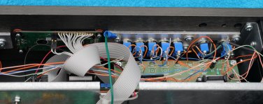
The switches on my AP17 are mounted to an aluminum plate. I had tapped holes installed on the back side of the front panel that are used to mount the aluminum plate. The holes for the switches themselves were also drilled out on the back side of the front panel, to accommodate the nuts holding the switches to the aluminum plate. I'd be happy to send you my FPE design for the panel if you are interested. The photo below may be instructive (and also shows the L-brackets holding the front panel in place).
Regards,
Scott
The front panel on the Slimline chassis attaches to the two side panels via L-brackets. Removal and reattachment of the front panel is easy, provided you can get access to the two bolts that hold each L-bracket to the side panel.
The switches on my AP17 are mounted to an aluminum plate. I had tapped holes installed on the back side of the front panel that are used to mount the aluminum plate. The holes for the switches themselves were also drilled out on the back side of the front panel, to accommodate the nuts holding the switches to the aluminum plate. I'd be happy to send you my FPE design for the panel if you are interested. The photo below may be instructive (and also shows the L-brackets holding the front panel in place).
Regards,
Scott
Attachments
Mark and Jason:
No disrespect intended for all of your fine work, but I'd second UKToecutter's request. Andy has done beautiful work on his various F5 Turbo boards and has received a lot of acclaim for his efforts. While diyaudio will probably offer alternate boards to make the V2 and V3 F5 Turbo amps (or instructions on how to modify your F5 "c" pcbs), I can also see benefits to (a) spreading MOSFETs out further than the UMS will allow and (b) supporting a member's contributions to the community.
Would you be adverse to offering an alternate PTH pattern consistent with Andy's F5T designs?
Regards,
Scott
Ah OK, I understand. Now the very thick front panel makes sense.pixpop:
The front panel on the Slimline chassis attaches to the two side panels via L-brackets. Removal and reattachment of the front panel is easy, provided you can get access to the two bolts that hold each L-bracket to the side panel.
The switches on my AP17 are mounted to an aluminum plate. I had tapped holes installed on the back side of the front panel that are used to mount the aluminum plate. The holes for the switches themselves were also drilled out on the back side of the front panel, to accommodate the nuts holding the switches to the aluminum plate. I'd be happy to send you my FPE design for the panel if you are interested. The photo below may be instructive (and also shows the L-brackets holding the front panel in place).
Regards,
Scott
I guess my question is why do we assume this is a fact: "The F5 Turbo will require a wide MOSFET spacing" Or more to the point. What IS wide spacing?
It seems that EUVL, who has studied heatsinks in some depth for his balanced F-5 (F5x) agrees in a way, but while his MOSFETS are widely spaced, they are clumped in the middle of the heatsink, AND stacked above each other. I don't think the quoted member would consider this "widely spaced" at all if looked at from the point of view of the first sentence here.
Our boards are quite long- about as long as will fit on a 300mm long heatsink.
If the MOSFETS are spaced in two pairs as in the F-5c boards you could argue that each pair is spaced very well, in that there is about equal heatsink on either side of the pair, towards the ends and towards the center.
I'm not arguing, but wondering if 2 widely spaced pairs is REALLY worse than: 4 evenly spaced MOSFETS where the outer MOSFETS get a lot more heatsink than the inner ones trapped in the middle.
Anyone have any data or hard knowledge about this?
So far, we already added 4 new holes specifically for the Turbo diodes.
Great idea re: the Galaxy cases but I have a quick question regarding the UMS.
The F5 Turbo will require a wide MOSFET spacing and I was wondering if the UMS could be extended to accomodate 4 MOSFETS at 80mm spacing.
Also, can you confirm what the usable inside dimension of the heatsink is on the 300mm and 400mm case?
Last edited:
Variac.
space the devices evenly apart.
Now allocate a width of heatsink to each device that is the same as the spacing centre to centre.
In this standard case the C/C = 80mm
each of the 4 devices gets 80mm of heatsink allocated to it.
The total length of the sink is 320mm.
That is the optimum location for a free standing sink with a single row of devices.
This is described in some of the manufacturers datasheets.
When we come to two rows, it gets a bit more complicated.
This complication is due to the upper part of the sink being cooled by the rising air coming up from the lower part of the sink.
The lower part is cooled by the ambient air.
The upper part is cooled by the preheated air.
The sink needs extra area to get rid of the same amount of heat.
This situation calls for the vertical allocation of sink height to be biased towards dissipation of equal amounts of heat.
This becomes quite complicated, although I have seen one software application that does the calculations for us.
More usually the manufacturer tells us how high each row of devices needs to be for that height of sink.
For a single row the height location is ~40% up from the bottom, (not 50% which is the geometrical centre).
Last edited:
Thanks for everyone's input. I've refrained from commenting yet as we asked Modu for more information last Friday based on your suggestions (they can be slow to respond) and I'll post an update as soon as we have more information. We're listening to all your feedback, and will do the best we can given some rather difficult logistical and financial parameters.
- Status
- Not open for further replies.
- Home
- Site
- Site Announcements
- The diyAudio Store (USA) soon to stock chassis – requesting your feedback!