I hope you are right... I did installed based in my previous 6P3P...One of my checkings was to unmount the opt trans. and check the label underside and with google check the colors (they are in chinese) ...they state red to plate and blue to B+ so I did that. I did not try reversed because my lack of knowledge if that way was going to blow up something....
Best Regards,
Jorge
You should have a bypass cap there across the 330ohm resistor from pin8 on output tube to ground - you should have a 470uF 35v cap there - that is there to keep the amp from oscillating.
At any rate - that wont fix your low output. Check to be sure you have your circuit wired properly from driver tube to output tubes. Unlikely BOTH output transformers are bad, more likely something is loose and not hooked up solidly. Start at the RCA inputs and follow your signal wires all the way to the output tubes plate and grid connections, also double check your ground connection to the speakers on the secondary side of the OPT. You're most likely missing something easy.
here's a snip from the internet about output transformer wire colors:
Is there a standard scheme for output transformer wire colors?
Derived from the ARRL Radio Amateur's Handbook:
Single-ended transformers:
Plate lead (pri.) -------------- blue (or brown)
B+ (power supply) lead --------- red
speaker (typ. +) (sec.) -------- green (or yellow)
speaker return (sec.) ---------- black
Hi Bob,
Thank you very much for your help, I appreciate.
The bypass cap I am referring to is the cathode resistor of the 6N1 driver tube. In my former amp there were only the 1k resistor in pins 3/8. In the new one there is a 1k resistor followed by a 100R and bypassed the 1k with a 100 mf cap. at the joint of the two cathode resistors there is the injection of the feedback from the 10k feedback resistor and 8 Ohm sec connection.
I am going to check all the connections for another time, I hope is a human fault...

Thanks
Jorge
Hi Bob,
Thank you very much for your help, I appreciate.
The bypass cap I am referring to is the cathode resistor of the 6N1 driver tube. In my former amp there were only the 1k resistor in pins 3/8. In the new one there is a 1k resistor followed by a 100R and bypassed the 1k with a 100 mf cap. at the joint of the two cathode resistors there is the injection of the feedback from the 10k feedback resistor and 8 Ohm sec connection.
I am going to check all the connections for another time, I hope is a human fault...
Thanks
Jorge
Ok thanks for clarifying - I built mine without any cathode bypass cap on the driver tube. That should make the amp sound better for sure. Check signal wiring I bet something is not connected.
Cheers,
Bob
Problem fixed
Hi,
Problem solved.
OPT transformers ok. I really do not have a good idea of what was the problem, but as Bob pointed (Thanks my friend... ) I reinstalled signal wiring and ground line and voila....all ok....now.
I only have a little faint of hum that I think is probably associated to messy wiring inside due to as I am still testing it is not routed correctly. Also, in one of my test I taked off the Choke and added a simple resistor and that can also inject power supply noise....Today I am going to reinstall the choke and route everything well....I will follow up....
Best Regards,
Jorge
Ok thanks for clarifying - I built mine without any cathode bypass cap on the driver tube. That should make the amp sound better for sure. Check signal wiring I bet something is not connected.
Cheers,
Bob
Hi,
Problem solved.
OPT transformers ok. I really do not have a good idea of what was the problem, but as Bob pointed (Thanks my friend...
) I reinstalled signal wiring and ground line and voila....all ok....now. I only have a little faint of hum that I think is probably associated to messy wiring inside due to as I am still testing it is not routed correctly. Also, in one of my test I taked off the Choke and added a simple resistor and that can also inject power supply noise....Today I am going to reinstall the choke and route everything well....I will follow up....
Best Regards,
Jorge
hello
i recently purchased this amp and made the 1n4007 diode mode on them rect' tube. however now after running for several days the amps keep blowing fuses. anyone know what could be causing this current draw? i ask if anyone has had a similar problem and knows off hand what the cause maybe.
cheers
i recently purchased this amp and made the 1n4007 diode mode on them rect' tube. however now after running for several days the amps keep blowing fuses. anyone know what could be causing this current draw? i ask if anyone has had a similar problem and knows off hand what the cause maybe.
cheers
hello
i recently purchased this amp and made the 1n4007 diode mode on them rect' tube. however now after running for several days the amps keep blowing fuses. anyone know what could be causing this current draw? i ask if anyone has had a similar problem and knows off hand what the cause maybe.
cheers
i should add that it was blowing fuses at power up and in the absence of all tubes.
Hi guys, i have just made a new case for my amp, and in the process of re-housing. My amp was ready made off ebay and i have just noticed that my amp has a couple of extra resistors and 100 uf caps fitted which i'm thinking of omitting, everything else seems the same, so thinking less is more, but my question is, i noticed on the parts list there is single a 220k resistor that i cant see on the schematic or building plans, any idea where this might go... or am i seeing/not seeing things right. Also, would anyone be up sending me a good view jpeg of there internal for reference. Any help as always is much appreciated.
Regards,
Lee
Regards,
Lee
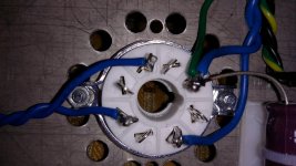
Hi there McGyver, if you meant the photos siliconray supplied, i was hoping for a more close, square view of the internals. I'm confident i know where everything goes (apart from that elusive 220k resistor) but would be nice to have a clear view of someone else's amp, just for reference. p.s. That's a beautiful set up, you got there McGyver.
I've just made a an outer case of mdf veneered with birds eye maple and aluminium plate which is cut and sprayed black, and ready to fit, not perfect but not bad for first attempt, no photos as of yet. Hopefully will upload when project is finished...the beautiful setup, i was referring to your link, assuming that's where you live and your audio system
And when you finish it, how about selling the old case? I'm looking for something like that to my prototype.
My system is here:

and details here: Mój system
My system is here:
and details here: Mój system
Hi, you can check it in our website for this 6p3p.
SiliconRay Online Electronic Store - Boards | Kits | Components | Modules | Tools
Hope this can help you. Thank you
SiliconRay Online Electronic Store - Boards | Kits | Components | Modules | Tools
Hope this can help you. Thank you
Hi, you can check it in our website for this 6p3p.
SiliconRay Online Electronic Store - Boards | Kits | Components | Modules | Tools
Hope this can help you. Thank you
Hi...
Have this kit good quality componets and are the quality all over good?
Thinking of ordering a kit to Norway...
Thx
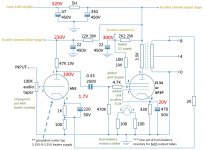
I have built the "improved" version of the amp (slightly different feedback loop design) and tested it pretty extensively. It works best as a SEP (single ended pentode); the driver stage does not have quite enough gain for triode mode unless you remove the feedback loop. The transformers are not great for triode mode; it sounds a bit boomy and slow, so I don't recommend triode. My schematic, posted below, sounds great and places the output tubes into pentode mode more safely than the original version (runs G2 at a lower voltage than the anode to avoid melting the screen grid). The original ties the screen grids to B+ and thus places them at a higher DC potential than the anodes.
It also sounds a lot better this way
I'm still not really convinced that 3.5K primaries are good for SEP mode for either an EL34 or a 6P3P, but I haven't done any calcs - just my gut tells me it should be higher.
By the way, get rid of that volume pot - channel balance is so far off it is a joke - it really doesn't cost much more to get an Alps - maybe you could offer it as an upgrade?
Attachments
- Status
- This old topic is closed. If you want to reopen this topic, contact a moderator using the "Report Post" button.
- Home
- More Vendors...
- Siliconray Online Electronics Store
- 6p3p tube amplifier kit