When you measured the Caps they were way of , the 330uF/450V I can not find but the nearest I can find is the 350uF/385 JJ Caps or should I go for the 500uF/500V ? Also I can not get the 22uF but instead can get 2X 10 uF or 1x 30uF .We do not have a signal tracer but if we do improve on the Tubes and Electrolytics we might be on our way to the Sound of Silence . Paul
Try this one for the 330uF from Farnel ES:
MAL215957331E3 - VISHAY - CAPACITOR, 330UF, 20% | Farnell España
For 22uf here:
UPW2G220MHD1TN - NICHICON - CAPACITOR ALUM ELEC, 22UF, 400V | Farnell España
These are from Farnell Spain...
I wouldn't use the 500uF if you don't have to, you can go up on uF not down ... C1, C2 & C3 values can be different than spec'd somewhat. The first cap don't go any higher than 47uF, you can go down to 20uF or so but no higher than 47uF. C2 can be anywhere from 220uF up to say 400uF but the higher you go the for uF the less filtering you get (generally speaking). What you want with a single ended amp is the BEST filtering you can afford.
You can bypass those caps with Polypropylene caps (retain the same or more voltages) bypass the 22uF with say .1uF bypass the 330uF with 3.3uF or so doesn't have to be exact there (1uF to 4uF) watch for sizes you want a small cap for bypass (connect the leads of the bypass cap to the + & - leads on the electrolytic caps).
Example for bypass cap:
ECWF2W105JA - PANASONIC - CONDENSADOR, 450V, 1UF, 5% | Farnell España
note the size - these can get too large so you need to be aware of that.
Cheers,
Bob
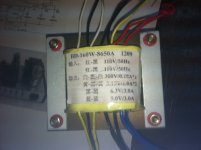
Hi Siliconray, I ordered you 6p3p amp kit, but the power transformer I received looks completely different than the transformer you posted earlier in the thread. Can you please label all the leads coming out of the transformer I received from you?
Attachments
I would like to add a power on indicator lamp. Can anyone suggest where along the circuit and how to go about it?
6.3V lamp - can get them at Radio Shack or angela instruments - use your 6.3V heater supply to power the lamp. Drill hole in chassis, mount lamp wire it from the 6.3V heater supply, it will turn on when you turn on your amp.
Here's a link to what they look like:
Blue Jewel Pilot Light Assembly For Tube Amp Projects.
Cheers,
Bob
I've read the threads on the Siliconray 6P3P and I'm looking forward to getting started on my build. This is an open ended question and I'm sure a lot of opinions, but as far as upgrades, which ones will give me the most bang for the buck? The best sonic improvements. New tubes, capacitors, transformers, resistors or volume pot?
Btw, thanks to everyone who has already provided such great info.
Paul
Btw, thanks to everyone who has already provided such great info.
Paul
I am considering buying one of these amps for driving the tweeters in my 3 way active system. I was using a Ming Da MC84-C PP amp, but it has terrible hum issues in my system. It works OK as a stand-alone amp, but doesn't like mixing in with the rest of my gear. If I can't resolve the hum problem, would one of these 6P3P amps work as a HF amp? 8 watts is plenty, but is the HF response delicate enough?
Any opinions? Changing caps and resistors is no problem, I have plenty of PIO and polyprop caps and resistors are cheap enough.
Any opinions? Changing caps and resistors is no problem, I have plenty of PIO and polyprop caps and resistors are cheap enough.
6p3p components explained.
Using the schematic for the SiliconRay 6p3p amp, I will attempt to explain in simple terms each component. You guys that know a lot more than I, please jump in to make any corrections.
Power Supply
Power supply transformer- transforms 120 (or 220) volt AC wall current from the primary winding into various AC voltages required by the amp. The secondary winding produces 300v power for the preamp and power tubes, and heater voltages for the tubes (6.3v for the power tubes, 5v for the rectifier tube, and 3.15v for the preamp tube).
5z4p rectifier tube - converts the 300 AC volts to DC for the preamp and power tubes.
Capacitors 47uf/450v, 330uf/450v, and 22uf/450v are filters which remove the ripples from the output of the rectifier tube, by passing the 60 (or 50) Hertz AC portion of the signal to ground, while allowing the smooth DC to be used as the B+ power for the preamp and power tubes.
Power supply choke coil 5H further smooths the DC signal by blocking any alternating current.
The 22k resistor and two 47k resistors decrease the voltage for use by the 6n1 preamp tube.
Amplifier
Potentiometer 100K acts as the volume control by adjusting the input level before passing it to the preamp tube.
6n1 is a dual triode tube, and amplifies both the left and right signals before reaching the main power tubes. The tube is heated through pins 4 and 5 with 3.15 volts from the power transformer. Amplification occurs as the low voltage signal input from pins 2 and 7 passes across the grid, and influences the movement of electrons from the negative cathode pins 3 and 8 to the positive plate pins 1 and 6.
1k resistors connected to pins 3 and 8 of tube 6n1 act to bias the preamp and keep the cathode at a more positive voltage compared to the grid.
0.33uf coupling capacitors block any DC portion of the 6n1 preamp output before entering the 6p3p power tubes.
470 k leak resistors set the level from the preamp output to the grid of the power tubes.
6p3p - pentode main power amp tubes. The tube is heated through pins 2 and 7 with 6.3 volts from the power transformer. Amplification occurs as the preamp signal output enters pin 5, passes across the grid, and influences the movement of electrons from the negative cathode pin 8, to the screen pin 4, and positive plate pin 3.
330k cathode resistors bias the tube and keep the cathode at a more positive voltage compared to the grid.
470u/35v cathode bypass capacitors act along with the cathode resistors 330k to provide bass reduction.
Output transformers - transform the high voltage, low amperage output of the 6p3p power tubes, to low voltage, high impedance required by either 4 or 8 ohm speakers.
10k resistors provide negative feedback to the 6n1 preamp tube from the output transformers, and slightly decrease the overall volume, but improve frequency response and decrease distortion.
- Status
- This old topic is closed. If you want to reopen this topic, contact a moderator using the "Report Post" button.
- Home
- More Vendors...
- Siliconray Online Electronics Store
- 6p3p tube amplifier kit