Stole this idea from Sijosae.. so I better share it...
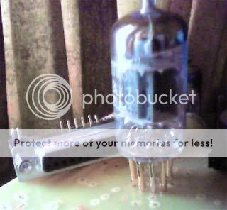
If you need a socket and the shop is closed...
pull the pins from an old female d-sub plug....
There you go, cheap gold contacts...
If you need a socket and the shop is closed...
pull the pins from an old female d-sub plug....
There you go, cheap gold contacts...
Filed for future reference!! 
These are the kind of tips that keep my projects rolling.
Cheers, Nordic.
These are the kind of tips that keep my projects rolling.
Cheers, Nordic.
I may never run out of miniature sockets (have plenty of salvaged ones) but recall that compactrons and Novar tubes have .040" (1 mm) pins as well...
I tried that waiting for acorn sockets to arrive and found the pins didn't retain tension well. A simple solution was slipping 1/8" of tight-fitting teflon sleeve over the sub-D pin before soldering, just enough to act as a tensioning band. Shrink tube might work too though not as well.
You can't get away with that Nordic!!!
What is it? (Headphone amp?)
What tube is that?
What supply does it run in on?
How do I build it?
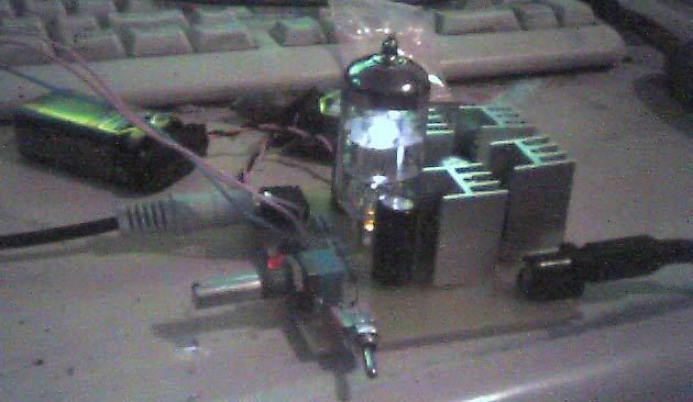
and .... I know it's so wrong ....... but I love the LED idea. 😉
What is it? (Headphone amp?)
What tube is that?
What supply does it run in on?
How do I build it?
and .... I know it's so wrong ....... but I love the LED idea. 😉
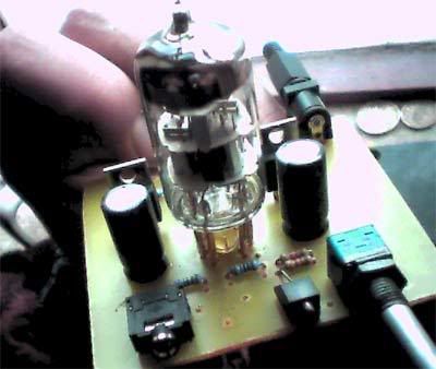
Yeah, its a Multi-Hybrid Headphone Amp
6922 - ecc88 - 6dj8 and a few cheap fets and regs...
24V and 2 9V cells, batteryless version explained too.
http://translate.google.com/transla...&hl=en&ie=UTF-8&oe=UTF-8&prev=/language_tools
and another version
http://translate.google.com/transla...&hl=en&ie=UTF-8&oe=UTF-8&prev=/language_tools
6922 - ecc88 - 6dj8 and a few cheap fets and regs...
24V and 2 9V cells, batteryless version explained too.
http://translate.google.com/transla...&hl=en&ie=UTF-8&oe=UTF-8&prev=/language_tools
and another version
http://translate.google.com/transla...&hl=en&ie=UTF-8&oe=UTF-8&prev=/language_tools
An externally hosted image should be here but it was not working when we last tested it.
An externally hosted image should be here but it was not working when we last tested it.
Success... after some innitial headscratching
my second ever valve project... and the second cheveat was.... I am using my PC steering wheel's 24V walwart.😀
Tommorrow I wil build Sijosae's V3 of the same thing...
my second ever valve project... and the second cheveat was.... I am using my PC steering wheel's 24V walwart.😀
An externally hosted image should be here but it was not working when we last tested it.
Tommorrow I wil build Sijosae's V3 of the same thing...

It might be worth pointing out that the pins on most pcb mount sockets do not line up with the pins on the tubes -- they are spaced wider. So, it looks like you designed the board with the eagle "tubes" library, and if you now try to fit a regular socket to the board, with a very few exceptions, it won't fit.
So, you may be stuck with the makeshift socket, and, importantly, someone with a board spaced for a socket who is lacking one likely won't get away with this trick.
So, you may be stuck with the makeshift socket, and, importantly, someone with a board spaced for a socket who is lacking one likely won't get away with this trick.
Hi D. yes, am aware of it... V3 is so tight no socket would fit anyway... this one is just to listen to for a day or so and to build some courage...
very sentimental, but beats any chip headphone amp I've build in sound quality area... only tiny bit of hum... but then again look at my psu
real hybrid.... 9V cells, smps, j-fets, mosfets, tubes, and regulators
very sentimental, but beats any chip headphone amp I've build in sound quality area... only tiny bit of hum... but then again look at my psu
real hybrid.... 9V cells, smps, j-fets, mosfets, tubes, and regulators
here is my one
just had finish the soldering job
i built the simple version because i cant find small pots here in my city.
regards
just had finish the soldering job
i built the simple version because i cant find small pots here in my city.
An externally hosted image should be here but it was not working when we last tested it.
regards
Diegot, please send me a link for the pcb ... looking for that one... etched the V3, but it is rediculously small... have seen tubes with a larger footprint.
The one I built is very unstable... it oscilates on power on... gotta pull the tube and reinsert with the power running to fix... then you have to adjust the trimpots to make noise go away.
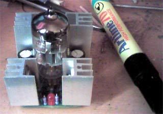
Then it sounds awesome I think the heatsinks on my IRF610s are too small... we are talking very hot.... Wonder if grid stoppers would help.
The one I built is very unstable... it oscilates on power on... gotta pull the tube and reinsert with the power running to fix... then you have to adjust the trimpots to make noise go away.
Then it sounds awesome I think the heatsinks on my IRF610s are too small... we are talking very hot.... Wonder if grid stoppers would help.
Nordic
I made the PCB of this link
http://www.headphoneamp.co.kr/bbs/zboard.php?id=diy_sijosae&no=247
Mine is rock solid. At the start up have a few seconds delay and then the sound starts. Very good but I have a little of hum, because i'm not using a regulated power supply yet. No grid sttopers required and it's pluged direct in the source, no volume control.
I just adjusted the trimpots just once, since then everything is fine.
I'm having 17V at the anodes but 7.3V at heaters, I need a larger resistor value on the 317.
At the output I'm using IRF530, wanna to try the 610 or 510 because their input capacitance, many times smaller than the 530, so I hope to get better treble.
The heatsinks are pulled of from a old At power supply and get real hot too, but I think that is fine for 2W of dissipation, I have two heatsinks.
Any problems you have I'm avaiable to help.
Regards,
Diego
Thanks, mine.....
still got to wire up pots... get new irf610s for the long legs, and then want to mount to base of CPU cooler...
still got to wire up pots... get new irf610s for the long legs, and then want to mount to base of CPU cooler...
- Status
- Not open for further replies.
- Home
- Amplifiers
- Tubes / Valves
- Cheap emergency gold sockets