hi
Everything tells me, that AD797 is not only a very good operational amplifier
The topology used has got to be something extremely good!
Using only the simplified schematic from Analog Devices datasheet
I get some extraordinary simulation results.
(And I am used to see a few good figures, from my own circuits. Using same transistors.)
===============================
A few details from me, for those who want to try to make a better AD797 Clone.
... but I am not sure anyone could do this better than myself
... maybe get some similar results, but not better, I doubt.
My circuit is in attachment and follows the AD797 schematic
- what I know from reading This Datasheet Very Closely
Good Luck Fellowes!
You may need really it 😀
Regards
lineup
Everything tells me, that AD797 is not only a very good operational amplifier
The topology used has got to be something extremely good!
Using only the simplified schematic from Analog Devices datasheet
I get some extraordinary simulation results.
(And I am used to see a few good figures, from my own circuits. Using same transistors.)
===============================
A few details from me, for those who want to try to make a better AD797 Clone.
... but I am not sure anyone could do this better than myself
... maybe get some similar results, but not better, I doubt.
My circuit is in attachment and follows the AD797 schematic
- what I know from reading This Datasheet Very Closely
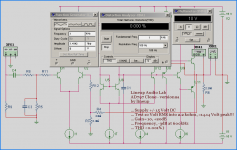
Lineup Audio Lab
AD797 Clone - version 2a
by lineup
... Supply +/- 15 Volt DC
... Test 10 Volt RMS into 2.2 kohm, = 14.14 Volt peak!!!
... Gain= x10, +20dB
... Frequency, -3dB at 600kHz
... THD <0.001%, my MultiSim does not show anything = 0.000%, see picture
Some more details:
All transistors BC550C and BC560C.
Total Supply Current 8.0 mA
Output stage, like the original biased only 0.5 mA ( 492uA more precise .... )
Good Luck Fellowes!
You may need really it 😀
Regards
lineup
Attachments

lineup said:hi
Everything tells me, that AD797 is not only a very good operational amplifier
The topology used has got to be something extremely good!
Using only the simplified schematic from Analog Devices datasheet
I get some extraordinary simulation results.
(And I am used to see a few good figures, from my own circuits. Using same transistors.)
===============================
A few details from me, for those who want to try to make a better AD797 Clone.
... but I am not sure anyone could do this better than myself
... maybe get some similar results, but not better, I doubt.
My circuit is in attachment and follows the AD797 schematic
- what I know from reading This Datasheet Very Closely
Good Luck Fellowes!
You may need really it 😀
Regards
lineup
In the sim you have perfectly matched current sources, perfectly matched transistors, of course your THD is close to zero.
Jan Didden
Re: AD797 Clone people!
The above was an AD797 Analog Devices operational amplifier CLONE.
Where I tried to make as perfect discrete copy as possible
of this high very performance and expensive AD797
I now have used same basic topology, with some changes
to try to get some other 'improved features and data'.
The circuit still has got a diamond output buffer,
but here I have used Low Noise High Voltage JFET 2SK373, 100V, for input pair.
Instead of low-noise bipolar BC550C, 45V
And 150V transistors 2N5551 - 2N5401 for rest of this amplifier.
This gives my New Op-Amp Max supply of 100 VDC, or Dual supply +/-50 Volt.
Test results at unity gain and +/- 40 VDC
were performed at 1kHz
- 20 VRMS input = output. Peak: 28.9 volt input ... 28.3 volt out
- Into 2 kOhm resistor LOAD
THD shows 0.000%
See link below for Fourier analys of Separate Harmonics.
================================================
My simulation test setup of this discrete Op-Amp here:
http://www.diyaudio.com/forums/attachment.php?s=&postid=1085465&stamp=1166531312 (image)
Read more details of this Lineup Audio Project
and about 2SK373 JFET for 100 Volt
in this post:
Extreme Performance Discrete Op Amp - 2SK373 2N5551 2N5401
Regards
lineup 😎 discrete op amp man
lineup said:
Using only the simplified schematic from Analog Devices datasheet
I get some extraordinary simulation results.
A few details from me, for those who want to try to make a better AD797 Clone.
... but I am not sure anyone could do this better than myself
... maybe get some similar results, but not better, I doubt.
My circuit is in attachment and follows the AD797 schematic
.
The above was an AD797 Analog Devices operational amplifier CLONE.
Where I tried to make as perfect discrete copy as possible
of this high very performance and expensive AD797
I now have used same basic topology, with some changes
to try to get some other 'improved features and data'.
The circuit still has got a diamond output buffer,
but here I have used Low Noise High Voltage JFET 2SK373, 100V, for input pair.
Instead of low-noise bipolar BC550C, 45V
And 150V transistors 2N5551 - 2N5401 for rest of this amplifier.
This gives my New Op-Amp Max supply of 100 VDC, or Dual supply +/-50 Volt.
Test results at unity gain and +/- 40 VDC
were performed at 1kHz
- 20 VRMS input = output. Peak: 28.9 volt input ... 28.3 volt out
- Into 2 kOhm resistor LOAD
THD shows 0.000%
See link below for Fourier analys of Separate Harmonics.
================================================
My simulation test setup of this discrete Op-Amp here:
http://www.diyaudio.com/forums/attachment.php?s=&postid=1085465&stamp=1166531312 (image)
Read more details of this Lineup Audio Project
and about 2SK373 JFET for 100 Volt
in this post:
Extreme Performance Discrete Op Amp - 2SK373 2N5551 2N5401
Regards
lineup 😎 discrete op amp man
As janneman hinted earlier, anyone can build a 'perfect' circuit in a simulator. There is a great deal of difference between the fantasy of perfect components and the reality of imperfect parts out in the real world. Even matched transistors do not approach the ideal units in a simulator.
Grey
Grey
The proof lies in tossing out the sim, buying some components and protoboard, building the sucker an then measuring actual THD (and other relevant stats).
Bitter experience teahes that sims and reality are ofter far apart.
Bitter experience teahes that sims and reality are ofter far apart.
ashok said:Lineup......What software are you using for analysis ?
Thanks.
Ashok.
That's the Multisim/EWB.
Is it possible to use diamond buffer output stage for low biased classAB power amplifier (bias about 25-50mA)? Or is that diamond buffer output stage is only good for classA?
A few years ago I built myself a headphone amplifier that was basically a vanilla 3-stage power amp with a very abbreviated output stage (mje340+mje350). Way overkill for a headphone amp but after I was done I realized it could work well as a single stage pre-amp. Then the light hit me that with a couple of trace cuts and added jumpers I could convert it into a discrete opamp. ( You could even say it had always been an opamp amp but I didn't realize it. )
I messed with it enough to convince myself it really functioned as an opamp. Functionally it was not too bad -- hardly equivalent to the A797 but a cut above an old LM741. I didn't have a use for it so I didn't pursue the matter. A few couple of month's ago I discovered Randy Slone had done something similar but more elaborate -- a class-A bias circuit similar to one of his power amp designs instead of my lowly green LED - four per PCB (discrete quad opamp?) etc. Any way I was pleased I had stumbled on the same idea independently even if my execution wasn't in the same league.
While a discrete opamp is interesting and fun, so far the real practical (in the sense of advantage over an IC) application I can think of would be when you really want/need to have higher rail voltages.
Hi lineup.
Warnin simulation is not a reality.
AC versus TRANSIENT look_
AD797 in input 12+12 transistors::::: LOW NOISE tech.
Better schematics OPA 646_?
ad797 is patented as Burr Brown ampz
Warnin simulation is not a reality.
AC versus TRANSIENT look_
AD797 in input 12+12 transistors::::: LOW NOISE tech.
Better schematics OPA 646_?
ad797 is patented as Burr Brown ampz
Re: Hi lineup.
AD797 is made by Analog Devices, not Burr-Brown

OPA646 is obsolete/discontinuedhastros said:Warnin simulation is not a reality.
AC versus TRANSIENT look_
AD797 in input 12+12 transistors::::: LOW NOISE tech.
Better schematics OPA 646_?
ad797 is patented as Burr Brown ampz
AD797 is made by Analog Devices, not Burr-Brown
Hi,
AD talk about "pairwise device matching".
Which pairs need to be matched?
Q1&2, Q5&6, Q3&4, Q8&11, Q9&10, Q12&?
What characteristics need to be matched and how close?
AD talk about "pairwise device matching".
Which pairs need to be matched?
Q1&2, Q5&6, Q3&4, Q8&11, Q9&10, Q12&?
What characteristics need to be matched and how close?

Q7 Base
should be at Q4 collector = The output to buffer.
There might be some other faults, too
... like C1 NOT to Emitter, but Collector of Q5. If I remember AD797 circuit.
Your picture is not 100%, so Try those changes first.
Then we see what happen.
You may also adjust R3 (1mA current).
Make it a TRIMMER, because it is important to adjust R3!
Remember will be 2mA across each R1, R2 !!!!!
So logical: R3 = 2 x R1.
Something like ~2 times. Adjust trimmer R3 for best balance!
christmas
lineup
Attachments

- Home
- Amplifiers
- Solid State
- AD797 Clone people! Who can make a better one.