I listened only to a crocodile clip-style setup, but I was pleased to hear non-aggressive highs, not exactly smooth, but exact and neutral, I could tell grainy sounds from clean sounds on pop recordings. I think it's all there, maybe not 100%, but 90?? 80?? don't know. I changed the ground connection from TDA1543 to CS8412 to the dgnd pin already.
Hello Doede,
I had 8 of them side by side, I am still thinking back of it, sounded good, but had no soundstaging and lacked definition (your design") but on my own P2P board and the board matters I think now...)
but on my own P2P board and the board matters I think now...)
like BG's? I have decided to not wait 300 hours to judge a capacitor. But a few small ones aren't that expensive and maybe I will try them, but judge quicker
Optimally, I want to get the design right first with standard caps, but the published curves of those Oscons have advantages in high frequency that's why I used them without additional bypassing to decouple the opamp and TDA here.
Regards,
Lukas
that's what I had til now. While sounding tonally good, I always found them lacking some definition, especially in the highs. So I wanted to try this one out.dddac said:Hi 12 Cents,
If you are in to play around a bit with your DAC:
have you tried listening without the opamp? so with passive I/V?
you might want to stack a few 1543 and try that....
I had 8 of them side by side, I am still thinking back of it, sounded good, but had no soundstaging and lacked definition (your design
but on my own P2P board and the board matters I think now...)and what about some real good capacitors?
doede
like BG's? I have decided to not wait 300 hours to judge a capacitor. But a few small ones aren't that expensive and maybe I will try them, but judge quicker
Optimally, I want to get the design right first with standard caps, but the published curves of those Oscons have advantages in high frequency that's why I used them without additional bypassing to decouple the opamp and TDA here.
Regards,
Lukas
Lukas:
Why don't you build a tower with 8 (or 16 ) DACs, in Doede's way? That will limit signal path length to a minimum and probably improve the faults you noticed.
I use Doede's excelent DAC with a 16* tower with some Elna Starget caps and Riken-Ohm load R and it really sounds very good (appart a small HF distorion that is completelly my fault as it wasn't there when I build it ). Appart that, output coupling caps are critical!
Dear Doede:
Any news about your 60*DAC?
Best of luck.
Mauricio
I had 8 of them side by side,
Why don't you build a tower with 8 (or 16
) DACs, in Doede's way? That will limit signal path length to a minimum and probably improve the faults you noticed.I use Doede's excelent DAC with a 16* tower with some Elna Starget caps and Riken-Ohm load R and it really sounds very good (appart a small HF distorion that is completelly my fault as it wasn't there when I build it
). Appart that, output coupling caps are critical!Dear Doede:
Any news about your 60*DAC?
Best of luck.
Mauricio
maxlorenz said:Lukas:
Dear Doede:
Any news about your 60*DAC?
sure: prototypes work superb, testing shows increased stage and definition when switched from 24 to 60 dacs
With a USB to I2S converter (next prototype which is ready) a next big step is made (SPDIF clearly is a limitation !)
This converter works with a 12MHz Tent clock by the way and on board low noise power supply (from the DAC battery)
Hope to publish end of december (time... time...)
doede
Doede:
I'm glad to hear (read) that
I'm building a CD-PRO2M based transport and would love to use your new DAC directly fed by its I2S output, inside the box.
Also, in the next future I plan to feed the DDDAC with ALW Super Regulators, and try get rid of the battery (my dad has a 1934 Mercedes Benz wich could use it )
Best wishes.
Mauricio.
I'm glad to hear (read) that
I'm building a CD-PRO2M based transport and would love to use your new DAC directly fed by its I2S output, inside the box.
Also, in the next future I plan to feed the DDDAC with ALW Super Regulators, and try get rid of the battery (my dad has a 1934 Mercedes Benz wich could use it
)Best wishes.
Mauricio.
maxlorenz said:Doede:
I'm glad to hear (read) that
I'm building a CD-PRO2M based transport and would love to use your new DAC directly fed by its I2S output, inside the box.
you better have a really LARGE enclosure - unless you don't want to take it to to the full 60 DAC chips
I've seen pictures of his test rig and if you're planning on anything smaller than a full-sized rack enclosure for your transport, you'll have to compromise on the TDA1543 count or rig up a secondary enclosure just for the DAC.
Peter
Lukas:
Remember, by adding more DAC's you will increase current output and could lower R load to desired Vout. "The best opamp is no opamp"
I use 120R and bass/midbass are terrific, with very dynamic sound.
Playing with different resistor types is easy and cheap (only 2) to fine tune the sound.
I choose Riken because I like them and also because Peter Daniel advised it.
Peter:
Thanks for the info.
I built a large box planning to add a DDDAC or the 60*DAC. I won' need the receiver part of the circuit , I think. I hope final product will diminish in size.
Best wishes.
Mauricio
maxlorenz said:
Peter:
Thanks for the info.
I built a large box planning to add a DDDAC or the 60*DAC. I won' need the receiver part of the circuit , I think. I hope final product will diminish in size.
Best wishes.
Mauricio
I meant BIG - to get to 60 chips, you will have to fit five PCBs in there. The receiver board is the least of your space problems
Peter
maxlorenz said:"The best opamp is no opamp"
Why?
I have the idea of the MKV caps from Peter Daniel, too. There were for sure others who used them for long times, I think I saw them on german tube forums already, but doesnt all matter, if we all get the sound we want.
Best regards,
Lukas
Why day
Dear Lukas:
Why? Based on my limited understanding, the least elements on the signal path the best.
Why add an opamp if you already have all the gain you need with a DAC tower? Simpler, cheaper and better sounding, IMHO.
Please take a look at Doede's site
Dear Peter:
Why do we need 5 separate boards for the towers?
I could build a big tower and place it horizontally, with PCB placed vertically, or four 15 DAC tower placed side by side in one board.
Dear Lukas:
Why? Based on my limited understanding, the least elements on the signal path the best.
Why add an opamp if you already have all the gain you need with a DAC tower? Simpler, cheaper and better sounding, IMHO.
Please take a look at Doede's site
Dear Peter:
I meant BIG - to get to 60 chips, you will have to fit five PCBs in there
Why do we need 5 separate boards for the towers?
I could build a big tower and place it horizontally, with PCB placed vertically, or four 15 DAC tower placed side by side in one board.
Re: Why day
Yeah, I've done that, great site.
But how about decoupling from cable issues, what about back EMF, next input stage load, low output impedance? BTW in the output signal of our NOS DAC is very high frequency contained, maybe we should think of cable termination and impedance matching to minimize the risk of reflections on that line.
Lukas
maxlorenz said:Based on my limited understanding, the least elements on the signal path the best.
Why add an opamp if you already have all the gain you need with a DAC tower? Simpler, cheaper and better sounding, IMHO.
Please take a look at Doede's site
Yeah, I've done that, great site.
But how about decoupling from cable issues, what about back EMF, next input stage load, low output impedance? BTW in the output signal of our NOS DAC is very high frequency contained, maybe we should think of cable termination and impedance matching to minimize the risk of reflections on that line.
Lukas
Re: Why day
The problem is the power supply for the DAC tower.
My 16 chip DAC needs a seriously huge heat sink to dissipate the heat of the 8.5V regulator, and 16 chips are just pulling 2 amps. The 60 chip version, if driven all at once by the same supply, will be pulling almost 8 amps, and half of that goes into heat at the regulator. You know any parts that can handle that? I had to shave off voltage with some power resistors to control the heat in my DAC, but the regulator still generates a lot more heat than the DAC stack does. I've been pricing large wheel chair batteries - the old 15 pound 18ah cell I got now isn't gonna cut it when the big one gets built!
If you're not planning on SLA battery power, and instead use an AC/DC supply with unregulated DC closer to the 8.50V DC that's needed, you may be able to drop the heat loss a little, but you're still not going to find a single regulator that'll handle 8 amps and be nice and quiet.
On the other hand - there's nothing that'll stop you from completely custom building it, with regulators for sections of your 60 chip tower, but then that's a lot of extra stuff you need to fit into the case...
Peter
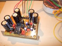
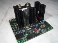
PS - here's what a 16 chip unit takes:
http://didnt.doit.wisc.edu/audio/DDDAC16/dddac16.html
maxlorenz said:
Why do we need 5 separate boards for the towers?
I could build a big tower and place it horizontally, with PCB placed vertically, or four 15 DAC tower placed side by side in one board.
The problem is the power supply for the DAC tower.
My 16 chip DAC needs a seriously huge heat sink to dissipate the heat of the 8.5V regulator, and 16 chips are just pulling 2 amps. The 60 chip version, if driven all at once by the same supply, will be pulling almost 8 amps, and half of that goes into heat at the regulator. You know any parts that can handle that? I had to shave off voltage with some power resistors to control the heat in my DAC, but the regulator still generates a lot more heat than the DAC stack does. I've been pricing large wheel chair batteries - the old 15 pound 18ah cell I got now isn't gonna cut it when the big one gets built!
If you're not planning on SLA battery power, and instead use an AC/DC supply with unregulated DC closer to the 8.50V DC that's needed, you may be able to drop the heat loss a little, but you're still not going to find a single regulator that'll handle 8 amps and be nice and quiet.
On the other hand - there's nothing that'll stop you from completely custom building it, with regulators for sections of your 60 chip tower, but then that's a lot of extra stuff you need to fit into the case...
Peter
PS - here's what a 16 chip unit takes:
http://didnt.doit.wisc.edu/audio/DDDAC16/dddac16.html
Dear Lukas said:
Oh! you're right...more homework to do after new amps building 
Low impedance, I think we already have it.
As for the HF contention, since I use BG N output caps (super E-cap) I don't miss HF extension.
Dear Peter said:
I see your point very clearly. Thanks. The way to go maybe is 4 regs, each one for each DAC tower. I planned to use a battery. I already use a 34Ah one: +/- 17 hrs of music for 16*DAC.
Anyway I was hoping that Doede solved this problem for us
Eight amps, maybe we can avoid using power amps
Many thanks for your teaching effort. It is greatly appreciated. In general I know nothing, but particularly in digital I know even less
One more question:
You maybe use heatsink for the tower itself. Do you ground your heatsink?
Thanks
Mauricio
But how about decoupling from cable issues, what about back EMF, next input stage load, low output impedance? BTW in the output signal of our NOS DAC is very high frequency contained, maybe we should think of cable termination and impedance matching to minimize the risk of reflections on that line.
Oh!
you're right...more homework to do after new amps building Low impedance, I think we already have it.
As for the HF contention, since I use BG N output caps (super E-cap) I don't miss HF extension.
Dear Peter said:
My 16 chip DAC needs a seriously huge heat sink to dissipate the heat of the 8.5V regulator, and 16 chips are just pulling 2 amps. The 60 chip version, if driven all at once by the same supply, will be pulling almost 8 amps, and half of that goes into heat at the regulator.
I see your point very clearly. Thanks. The way to go maybe is 4 regs, each one for each DAC tower. I planned to use a battery. I already use a 34Ah one: +/- 17 hrs of music for 16*DAC.
Anyway I was hoping that Doede solved this problem for us
Eight amps, maybe we can avoid using power amps
Many thanks for your teaching effort. It is greatly appreciated. In general I know nothing, but particularly in digital I know even less
One more question:
You maybe use heatsink for the tower itself. Do you ground your heatsink?
Thanks
Mauricio
Re: Why day
The issue is also, that you cannot drive without limitation any number of DAC chips.... Every data input pin is drawing some current and has a capacity...
I did some tests and I would say that above 20 you are running into to problems....
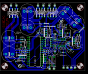
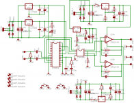
that is the reason I decided to design modules with 12 dac chips and every tower is buffered and ahs their own power supply. The modules has a I2S bus running from left to right, so you can keep adding 12-dac modules in a master slave configuration without loading the I2S source too much.
As an extra bonus you have a compact construction which helps also on managing the power disipation....
Just have a look at this picture from a DAC module, I will publish soon any way, so it won't harm to much if I show a quick peek
Doede
maxlorenz said:Why do we need 5 separate boards for the towers?
I could build a big tower and place it horizontally, with PCB placed vertically, or four 15 DAC tower placed side by side in one board.
The issue is also, that you cannot drive without limitation any number of DAC chips.... Every data input pin is drawing some current and has a capacity...
I did some tests and I would say that above 20 you are running into to problems....
that is the reason I decided to design modules with 12 dac chips and every tower is buffered and ahs their own power supply. The modules has a I2S bus running from left to right, so you can keep adding 12-dac modules in a master slave configuration without loading the I2S source too much.
As an extra bonus you have a compact construction which helps also on managing the power disipation....
Just have a look at this picture from a DAC module, I will publish soon any way, so it won't harm to much if I show a quick peek
Doede
Attachments
- Status
- This old topic is closed. If you want to reopen this topic, contact a moderator using the "Report Post" button.
- Home
- Source & Line
- Digital Source
- TDA1543 PCB design quest