Hi All
Let me know what you think of this headphone amp design.
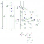
It is a combination of the Son of Zen amp and a bipolar-mosfet interpretation of the CFP.
The design simulated well so i am building it.
Instead of the BC549C's i am using a LM394 and i hand matched the resistors to 5dp's
I am really interested in hearing your feedback.
Thankyou
Tim
Let me know what you think of this headphone amp design.
It is a combination of the Son of Zen amp and a bipolar-mosfet interpretation of the CFP.
The design simulated well so i am building it.
Instead of the BC549C's i am using a LM394 and i hand matched the resistors to 5dp's
I am really interested in hearing your feedback.
Thankyou
Tim
Attachments
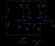
I just noticed I didn't include the transistor types in the circuit, so some of my previous post didn't make much sense.
Q1 and Q2 were simulated as BC549C's but i used a LM349 in the actual circuit.
M1 and M2, just about any P-Channel mosfet seemed to work. i simulated and used IRF9540's, cause i had them.
Q1 and Q2 were simulated as BC549C's but i used a LM349 in the actual circuit.
M1 and M2, just about any P-Channel mosfet seemed to work. i simulated and used IRF9540's, cause i had them.
paulb
I am already building my circuit!
I have finished the amplifer but i have yet to finish building the PSU, attenuator and the case.
i have had a brief listen to it, connected to a lab supply and it sounds really good, but i was running it from my rotel preamp and believe it can sounds even better with a passive stepped attenuator connected directly to my cd player.
I will attach some pics soon.
woody
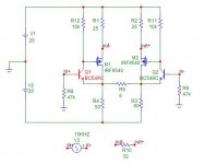
This circuit is an enhanced version of the son of zen, it has the advantages of improved linearity and wider bandwidth with the addition of just a few extra camponents. In fact either of the actual son of zens and the balanced zen line stage could be modifed to give improved performance with this mod (i might even do the sims on this and publish the results).
Though modifiing it to the supersymetric design is a really good idea and is something i should try out in the simulations")
Measurements:
The simulated measurements for the current design are such:
%THD @ 10kHz = 0.02%
%THD @ 1kHz = 0.015%
The -3dB bandwidth is 7Mhz (and probably should be reduced!)
The distortion figures are measured just before the onset of clipping, into a 32R load, and reduce from there.
Tim
I am already building my circuit!
I have finished the amplifer but i have yet to finish building the PSU, attenuator and the case.
i have had a brief listen to it, connected to a lab supply and it sounds really good, but i was running it from my rotel preamp and believe it can sounds even better with a passive stepped attenuator connected directly to my cd player.
I will attach some pics soon.
woody
This circuit is an enhanced version of the son of zen, it has the advantages of improved linearity and wider bandwidth with the addition of just a few extra camponents. In fact either of the actual son of zens and the balanced zen line stage could be modifed to give improved performance with this mod (i might even do the sims on this and publish the results).
Though modifiing it to the supersymetric design is a really good idea and is something i should try out in the simulations
Measurements:
The simulated measurements for the current design are such:
%THD @ 10kHz = 0.02%
%THD @ 1kHz = 0.015%
The -3dB bandwidth is 7Mhz (and probably should be reduced!)
The distortion figures are measured just before the onset of clipping, into a 32R load, and reduce from there.
Tim
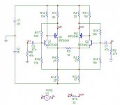
supersymmetric headphone amp
Well i have converted the simulation of my enhanced son of zen headphone amp to the supersysmmetric layout like zen v6 and I cannot improve its performance over my original design. But her is what i have come up with:
Well i have converted the simulation of my enhanced son of zen headphone amp to the supersysmmetric layout like zen v6 and I cannot improve its performance over my original design. But her is what i have come up with:
Attachments
ESOZ Heaphone Amp
I have been thinking about what to call my son of zen modifications, originally it was going to Son Of Zen + but now I think I will call the Enhanced Son of Zen or ESOZ for short. I hope Nelson Pass doesn't mind the usage of his zen name in my designs.
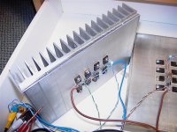
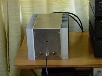
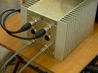
As promised I was going to post some constructional pics of my amp.
The first one is the amps on their heatsink.
I guess people, who havn't simulated it already, are wondering why such large heatsinks for a headphone amp! The reason is because I believe there is no such think as too much headroom...This design runs ~400mA in each half of the design for a total of ~800mA current per channel, which means this amp is dissapating ~32 Watts of heat per channel!
Tim
I have been thinking about what to call my son of zen modifications, originally it was going to Son Of Zen + but now I think I will call the Enhanced Son of Zen or ESOZ for short. I hope Nelson Pass doesn't mind the usage of his zen name in my designs.
As promised I was going to post some constructional pics of my amp.
The first one is the amps on their heatsink.
I guess people, who havn't simulated it already, are wondering why such large heatsinks for a headphone amp! The reason is because I believe there is no such think as too much headroom...This design runs ~400mA in each half of the design for a total of ~800mA current per channel, which means this amp is dissapating ~32 Watts of heat per channel!
Tim
Attachments
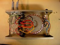
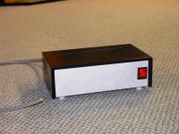
I am thinking of getting a bigger box because the one i ordered is a little flimsy for the size of the transformer. Another think i am planning to do is add inductors to the filtering but i will see how this sounds first.
Here is the PSU from the front:
Tim
Here is the PSU from the front:
Tim
Attachments
Sorry guys but i have not had a good chance to listen to it yet.
Well not since I brought it home once, with the heatsinks sitting in the pic, and manage to trip on my headphone cord causing the input transistor to short and destroy themselves and the outputs of my preamp!
So now i am waiting, in eager antisipation, for the case and the input attenuator to be finished and then i can have a good listen.
Though the impression i did get was of being quiet and transparent. Also the bass seemed less or maybe more detailed, it was hard to tell, but then it i could just be my grado's
Oh yeah, i stuck with my original circuit.
I have been playing with other ideas,
Like JFET input which has better stability than the mosfet but higher distortion. I guess it depends on what will sound better.
And applying these concepts to the real SOZ and Zen 6
Listening tests
I have finally put it together and have spent the last two weeks listening to it and most of my music collection.
I am not good at describing what i hear but I think it sounds really good! With a very transparent detailed sound.
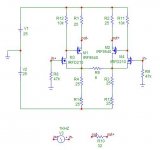
I have modified the circuit a little, it is running on a single supply rail and have added a simple high speed low noise regulator to reduce any ripple to way into the noise floor and now it is incredably quiet.
One downside with this design is the channels are too isolated and the sound stage is between my ears, so i am planning to add a natural crossfeed circuit (but balanced) as in Jan Meiers circuit:
http://headwize.com/projects/showproj.php?file=meier_prj.htm
Another idea i have had it to use it as a balanced preamp, i just have to sort out a suitable balanced volume control and to use it to drive my new balanced supersymmetry amp.
I have attached the modifed circuit and I will have to post some pics of it completed design, it looks like a headphone amp on steriodsjavascript:smilie('')
Enjoy
Tim
I have finally put it together and have spent the last two weeks listening to it and most of my music collection.
I am not good at describing what i hear but I think it sounds really good! With a very transparent detailed sound.
I have modified the circuit a little, it is running on a single supply rail and have added a simple high speed low noise regulator to reduce any ripple to way into the noise floor and now it is incredably quiet.
One downside with this design is the channels are too isolated and the sound stage is between my ears, so i am planning to add a natural crossfeed circuit (but balanced) as in Jan Meiers circuit:
http://headwize.com/projects/showproj.php?file=meier_prj.htm
Another idea i have had it to use it as a balanced preamp, i just have to sort out a suitable balanced volume control and to use it to drive my new balanced supersymmetry amp.
I have attached the modifed circuit and I will have to post some pics of it completed design, it looks like a headphone amp on steriodsjavascript:smilie('
')Enjoy
Tim
Attachments
- Status
- This old topic is closed. If you want to reopen this topic, contact a moderator using the "Report Post" button.
- Home
- Amplifiers
- Headphone Systems
- Son of Zen+, Headphone Amp