After a long time I almost have my boards ready.
I am using till now an Upsampling DAC from Elektor magazine but I want to replace the analog stage because it has opamps with something better.
I made a stereo version of the D1 I/V stage on one board direct for tweaking CD Players and DACs.
My Dac has 2 PCM 1704 and 4 opamps for the I/V and filter stages.
I will be posting pictures later on.
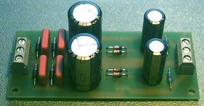
This is the actual stage with two stages on one PCB. You could actually use it for balanced signal also.
I use the signals singel ended so use only one board.
The Mosfets are missing from the PCB but all other parts are on it.
Silver Mica CAPs for the filter part. Audyn 4,7uF in series with the output. Welwyn 1% low noise resistors. Panasonic FC electrolytics.
I use the signals singel ended so use only one board.
The Mosfets are missing from the PCB but all other parts are on it.
Silver Mica CAPs for the filter part. Audyn 4,7uF in series with the output. Welwyn 1% low noise resistors. Panasonic FC electrolytics.
Attachments
promitheus said:
The Mosfets are missing from the PCB but all other parts are on it.
I was wondering where those FETs were.
 Need to read the text before I look at the pretty pictures.
I was looking to do something very similar myself to an old Denon player, D1 output + 1704, balanced out. Do you have your DAC board documented anywhere?
Keep us informed.
Rob
So it´s finished at last. I could only test one channel for the moment because I have to make some changes on the DAC board.
I took the opamps off but I have to desolder a few resistors and capacitors or they will effect the signal.
Setting the DC voltage of the input isn´t so easy and stable as I thought but it stays in the range +/- 10 mV.
Does anybody know how much this should be max. ?
It doesn´t effect the sound though which I can say is super super clear.
I also made a few corrections on the PSU after burning 2 diodes in the bridge. That´s what happens when you try to test it 2:00 clock at night.
Attachments
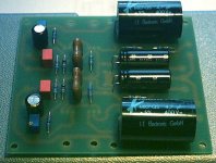
The inputs are at the top of the picture and you can see in the top corners the 2 small trimmers. With these you set DC offset at the input to 0V.
I use the PCM 1704 which has a current output like many DACs and the voltage there must be at 0 Volts.
The outputs are at the bottom where the 2 Audyn Caps are.
I use the PCM 1704 which has a current output like many DACs and the voltage there must be at 0 Volts.
The outputs are at the bottom where the 2 Audyn Caps are.
Hello Promitheus.
I've got somewhere at home the Elektor dac with pcm 63K which I've done several years ago.
If you're going to post the gerber files or ( for me better) pdf or any graphic file for the pcb, I'll be very happy to revamp that DAC and see what's going to happen with it and yor output stage
I'm confident that with such a design it will work much better that now.
Bye
Paolo
pdf
http://www.pdffactory.com/
Try this link for pdf.
They have a trial version to download ( about 2.8 M)
Don't know if this will work because i have not any knowledge about your pcb design system.
thanks and bye
Ciao
Paolo
http://www.pdffactory.com/
Try this link for pdf.
They have a trial version to download ( about 2.8 M)
Don't know if this will work because i have not any knowledge about your pcb design system.
thanks and bye
Ciao
Paolo
A few people have been asking for pcbs.
The reason that I don´t give any pcbs away is that I only made one.
Second the layout isn´t 100% OK. It works very very good but the mounting has a small problem for my box.
The circuit works now for almost one year and I can say I wouldn´t change it. The quality is so clear and dynamic.
If more people are interested I could make new improved boards and give them away at a very reasonable price for DIYers.
Well it doesn´t take long to make a new improved version.
People who are interested in boards should post for how many boards they want.
Each board has 2 stages. That means if you have left right unbalanced you need 1 board and 1 power supply.
If you have left right balanced you need 2 boards and 1 power supply.
About the price it depends on how many boards you guys want and how many I will at the end order.
If a few people are interested I will ask for a price from the manufacturer.
Just keep me posted when someone is interested.
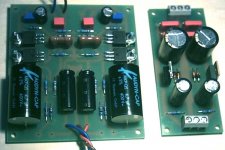
I just finished my D1 too :
P2P cabling :
http://phil.charlet.free.fr/images/dac/d1_1.jpg
not so beautiful, just one card (I am unbalanced on two chanels for now).
I wait for Welwyn resistor for the I/U resistor, panaFC for coupling caps and fkp2 for filtering caps. But until now, and with the components I had on the shelves, the result on my ad1865 dac is quite good.
http://phil.charlet.free.fr/images/dac/ensemble1.jpg
The vertical card is a guido clock with PSU and some reclocking logic :
http://phil.charlet.free.fr/images/dac/guidoclock.jpg
Philippe
promitheus said:
I have a pcb for a clock from ELSO WKAK on the forum but i have never used it. Is that from guido? Is it the same person?
No
- Status
- This old topic is closed. If you want to reopen this topic, contact a moderator using the "Report Post" button.
- Home
- Amplifiers
- Pass Labs
- D1 I/V Stage Finished.