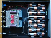
This morning I threw together my own version of the "Pacific Riaa Pre". I can now say that I have a completely Single Ended feedback-free amplifier chain (Pacific+BZLS+SOZ) 😀 And a really nice sounding chain it has become.. This crude little riaa pre is too good to be true. My intention is to tweak it like nothing has been tweaked before (cascoding etc), hence the "fast & furious" building style; it's very effective though (took me about 3 hours to make). All components are matched to the tightest tolerances and to get as close as possible to the ideal riaa values which are 22K4, 3K257 + 97n6, 100R + 33n5.
Well, enough rambling; do yourself a favour and try this circuit! 😉
Pictures:
Well, enough rambling; do yourself a favour and try this circuit! 😉
Pictures:
Attachments


you're too fast Magura 😉
I forgot to thank Thorsten; I was inspired by his "Pacific Optime" and am going to try his recommendations regarding this circuit. (Ref http://diyaudio.com/forums/showthread.php?postid=252211#post252211 )
I forgot to thank Thorsten; I was inspired by his "Pacific Optime" and am going to try his recommendations regarding this circuit. (Ref http://diyaudio.com/forums/showthread.php?postid=252211#post252211 )
Mad_K said:you're too fast Magura 😉
Nope....too slow, i already see your handwriting on the "back o' napkin" schematic 😉
....and guessing didnt do me much good

Magura🙂
Hehe... If you can't read it, you can't build it 😉 I could have drawn it in EWB5, but I like to draw on paper. I've got a "diy journal" where I scribble all my efforts. I'm an engineer; I can't think without a pen in my hand and a piece of paper in front of me.
With that handwriting...you could have become a doctor of medicine 😉
Would you mind to translate what youve written about the mosfets. Its a bit unclear to me, but lets blame it on the scanner 🙂
Magura🙂
Would you mind to translate what youve written about the mosfets. Its a bit unclear to me, but lets blame it on the scanner 🙂
Magura🙂
Well, scanning in 150dpi and compressing it to 100KB doesn't help much 😉
Here you go "Fets are 2SK170GR. Idss=4-6mA matched between channels per position."
Here you go "Fets are 2SK170GR. Idss=4-6mA matched between channels per position."

That looks horrible, but correct. You forgot the G-D-S on the second JFet 😉 Maybe I'll have to make a real schematic for you 
Considering its made in MS-Paint....its ugly but readable. The second fet is left out intetionally, since theyre identical.
Im fine with the "back o' napkin" solution, thats how i do schematics as well. I dont even have software for making schematics or simulation for that kind of matter.
Anyhow, its a great RIAA you made there....ill make a clone right away😀
Magura🙂
Im fine with the "back o' napkin" solution, thats how i do schematics as well. I dont even have software for making schematics or simulation for that kind of matter.
Anyhow, its a great RIAA you made there....ill make a clone right away😀
Magura🙂
What about substitutes for the SK170GR mosfets??
Any IR or On semi equalents (an ON semi cross ref. search didnt suggest any)???
Magura🙂
Any IR or On semi equalents (an ON semi cross ref. search didnt suggest any)???
Magura🙂
Magura said:
Anyhow, its a great RIAA you made there....ill make a clone right away😀
-I know, I'm going through my record collection like a Mad_Kman 😉
-Good for you.
BTW, have you read this? http://www.audionote.co.uk/anp2.htm
And this ? http://www.audionote.co.uk/anp1.htm (which I think is even better)
edit:
2SK147 and 2SK117GR are drop-ins. Don't really know about any IR or ON parts. Many JFETs can be used, but I believe the Toshiba parts are particulary good sounding units.
One other thing; you need to check the recommended load capacitance for you pickup and plan accordingly. I don't need any extra load C because my ClearAudio Virtouso Wood likes about 100pF and my cable is about 50pF and the Ciss of the 2SK170 is about 30pF pluss you can add a little to those numbers.
edit2: and don't even consider not to use batteries with this circuit... SLA's are recommended I think (and do get 3 of them so you can have more fun with cascoding etc later 😉 )
Thanks Mads
Ill make a PCB for this in the nearest future, then it will be a little easier to experiment with values without ending up with a bird nest 😉
Magura🙂
Ill make a PCB for this in the nearest future, then it will be a little easier to experiment with values without ending up with a bird nest 😉
Magura🙂
Nice! Then make room for a load C... I don't agree with you on the "easier to experiment" part, but we all do it the way we prefer.. We prototype HF circuits up to several GHz on gnd-planes and Mini MountTM at work, but it's obviously not for everyone. -A resistor change can be done in seconds 😉
I like to experiment on a PCB cause the risk that i get confused by something is smaller since the basic circuit is there. I usually CNC cut my PCB's so its no big deal to make such a proto board.
I know your way of doing prototyping is the RF way, and not bad, but it is confusing me to have such a mess of wires and components hanging on to a board in selected spots.
Magura🙂
I know your way of doing prototyping is the RF way, and not bad, but it is confusing me to have such a mess of wires and components hanging on to a board in selected spots.
Magura🙂
This setup is for MM, but you can use medium output MC provided you make the load R suitable for your pickup. If you need more gain, you could just insert one more JFet stage before the first one for about 90dB gain (it's about 54dB as drawn). Or use a stepup trafo.
edit: if you insert a third stage, the amp inverts the absolute phase.
edit: if you insert a third stage, the amp inverts the absolute phase.
- Home
- Source & Line
- Analogue Source
- Ultrasimple MM/MC RIAA preamp 2