
Just a quick point, but you do realise that these circuits do go against what was mentioned before in the other thread about the resistors being mathced for the + and - inputs to ensure minimum DC offset at teht output due to the input bias currents?
😕
😕
You are absolutely right. Some people are willing to put-up with some (up to 60mV) on the output (due to the imbalance at the input that you are talking about). I think the other problem would be the unpredictability of the offset (different amps have different Ib)
I'd sacrifice some purity and use a decoupling input cap.
That’s what I'm doing.
I'd sacrifice some purity and use a decoupling input cap.
That’s what I'm doing.
Attachments

i think a resistor in series with the noninverting terminal has been used for the purpose of DC offset protection. also, turning the ground for the feedback into a DC voltage will allow you to trim away the DC offset so that it is lower. this adds noise though.
theChris said:i think a resistor in series with the noninverting terminal has been used for the purpose of DC offset protection.
Not too sure what you mean here, which resistor do you mean, one of the feedback resistors? if so I'm still not too sure how this would provide DC offset protection (unless you are refering to the value of the lower feedback resistor being equal to the input resistor?), is there any chance you could explain this one to me a bit?
Squalish said:Is momentary DC something to worry about?
it wouldn't be dc then would it? in anycase, DC offset causes a turn on and turn off pop in most amps. annoying.
bigparsnip said:
Not too sure what you mean here, which resistor do you mean, one of the feedback resistors? if so I'm still not too sure how this would provide DC offset protection (unless you are refering to the value of the lower feedback resistor being equal to the input resistor?), is there any chance you could explain this one to me a bit?
in in series with the input basically. really from classic analysis it does nothing. kinda like the resistor to ground in the inverting config. ideally does nothing.
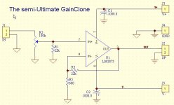
In the 2nd schematic, the resistor R1 changes the curve of the pot, and it's known as a shunt. It has nothing to do with DC.
This isn't quite true. You are correct, it changes the curve, but it does something else:
If the pot has some contact problems the full signal would be present on the input. the resistor provides some guaranteed minimum signal attenuation, will help the speakers to survive.
If the pot has some contact problems the full signal would be present on the input. the resistor provides some guaranteed minimum signal attenuation, will help the speakers to survive.
It's regarding the "semi-Ultimate"(2nd) sch.
R1 also keeps the +IN connected to GND with what seems to be the max allowable resistance of 22kOhm (based on the feedback I got from people that build NIGC) so that the output DC offset doesn’t go through the roof if there was no DC path for the + Ibiase trough GND. And that for sure will fry the speakers. If you can live with lower than 20k impedance R1 can be lower value (the lower the better for the output DC offset, the ideal being 680Ohm, but who can live with that low Input impedance).
I feel tempted:
The reference values in the picture bellow are for the "semi-Ultimate"(2nd) sch.
Attachments
JojoD818 said:GregGC,
May I ask what software you used to draw the schematic?
Best Regards,
JojoD
it's in the LM3875's datasheet
JojoD818 said:GregGC,
May I ask what software you used to draw the schematic?
Best Regards,
JojoD
Using PrintScreen (http://www.gadwin.com/printscreen/) captured the sch. from the pdf data sheet and then added the hand writing in ACDsee editing software (I think Paint Brush can do it too)
For the other sch. - Protel/PrintScreen.
GreGC,
I was talking of the other one, not the one off the datasheet. I see you use protel then.
Thanks,
JojoD
I was talking of the other one, not the one off the datasheet. I see you use protel then.
Thanks,
JojoD
hitsware, at another tread (http://www.diyaudio.com/forums/showthread.php?postid=260139#post260139)pointed out that OPA541/549 has jfet input (no worries for the Out DC offset), which I think makes it a very good candidate for the Ultimate/semi-Ultimate GC based on OPA541/549.
Greg
Greg
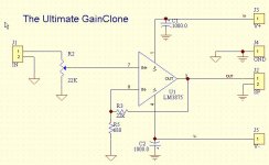
Regarding the two 1000uF caps, they are meant to be placed at the power supply aren't they, not at the chip? Or is that why some people say it is very important to have the PSU and Amp circuits within a few centimetres of each other?
Matt
Matt
The 1000uF caps should be near the chip, as close as possible. That way you eliminate the influence of the long connecting wires and provide proper decapling for the IC.
Read AN-202 from ANALOG DEVICE for more details.
You could connect small electrolytic on the side of the power supply. According to Peter Daniel's experience 4.7uF would be OK. Now you can do your own experiments with that. first though install the 1000uF as close as possible to the IC and than start increasing the capacitance on the power supply side until you get satisfactory to your liking results. You may find that more may not necessarily be sounding better. Personal preference dependant on the rest of your system.
Greg
- Status
- Not open for further replies.
- Home
- Amplifiers
- Chip Amps
- The Ultimat GainClone!