I would go for the second one, just so that all of the power amp chips are opperating int eh same mode, as with all the discussin on here about the varying performances of (non)inverting clones you may end up with a mildly unbalenced bridge setup.
Hi,
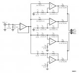
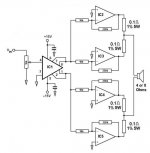
I have a working gc but it is in a non-inverting mode, can I still use the same topology as in the 2nd schematic?
Thanks,
JojoD
I have a working gc but it is in a non-inverting mode, can I still use the same topology as in the 2nd schematic?
Thanks,
JojoD
yes, you can do this with n/i amps, just change over the necesary parts, making sure you keep all of the critical components in the circuit.
What size and how many capacitors should be used on the rails? I currently have 1000 on each rail on my single channel IGC.
there are I believe two main schools of thought on htis one:
First: Place the same capacitance as you would for each single channel where you normaly would as though each chip was acting independantly of the others.
Second: Have one large bank of caps (as with a conventional PSU) and then use smaller decoupling caps close to each individual chip as before (but using much smaller caps than you normaly would).
I have noe experience of either of these layout (yet), but if this is a first attempt at this, I would use the one which is easier to implement for you at first, and if you are not happy you can easily change it later on (unless you use a PCB).
Andrew.
The 4 10K resistors and the 4 220K what tolerance should they be? Also who makes the .1ohm 5w 1% resistor?
Also can the 10k variable resistor ( I assume thats what it is on the signal input) be left out in favor for a preamp?
18v is the most the drv134 can handle, correct?
Also can the 10k variable resistor ( I assume thats what it is on the signal input) be left out in favor for a preamp?
18v is the most the drv134 can handle, correct?
The resistor tolerences for the feedback resistors should be as good as you can get them, idealy 0.1% or better.
Also, I would consider slightly larger output resistors (national recomend 0.22 as a minimum if I recall correctly, or else they may not work correctly) but I'm not too sure where you might find them (I know Dale produce high power and close tolerance wire wound type, and I think Vishay produce precision resisotrs in a T220 package which would run at 5W with a small heatsink).
As far as the DRV134 I'm not too sure, I would just go to naationals website and look it up in the data sheet.
bigparsnip,
What you said is what I have in mind! I'll build 4 usual channels, with the caps and decoupling caps and then make a bank of caps in the main psu.
The only problem I have is finding the 0.1ohms 5W 1%, we don't have such resistors here, just 5% 5W. Can I use that?
JojoD
What you said is what I have in mind! I'll build 4 usual channels, with the caps and decoupling caps and then make a bank of caps in the main psu.
The only problem I have is finding the 0.1ohms 5W 1%, we don't have such resistors here, just 5% 5W. Can I use that?
JojoD
0.1 ohm 5 watt resisitors? hmm. i think you could almost make that with a little bit of wire!
5% would be no good. were looking for matching here, not so much accuracy on each, but matching. it creates a network so each opamp will work equally as hard.
5% would be no good. were looking for matching here, not so much accuracy on each, but matching. it creates a network so each opamp will work equally as hard.
Hi,
AN1192 states that a 385VA trafo is needed per channel. One channel consists of 4 chipamps right?
JojoD
AN1192 states that a 385VA trafo is needed per channel. One channel consists of 4 chipamps right?
JojoD
Aside from the transformer question, do I still need to put zobel networks on each of the 4 chipamps?
Thanks,
JojoD
Thanks,
JojoD
Hi, the tollerence of the output resistors is not too critical when it comes down to it, as they are only there to make sure the chip amps share the current equaly between them, and if you can get this down so that there is no more than 5% difference between the chips that should be good enough (although, if you do want better, just buy more resistors than you need and match them up by yourself with a good multi meter).
As far as the Transformer goes, you will only need one for each speaker you use, so yes, one for each set of chip amps.
And if you do use a zobel, I think it wouild be ok to just yse one, placed directly at the output after all of current matching resistors.
As far as the Transformer goes, you will only need one for each speaker you use, so yes, one for each set of chip amps.
And if you do use a zobel, I think it wouild be ok to just yse one, placed directly at the output after all of current matching resistors.
bigparsnip,
Thanks for the info. I already have a 2 channel gc that works. My plan is to parallel my existing 2 channel and build another 2 channel and parallel it with the 0.1 ohms of course. Then I will bridge them with a drv134 (on it's way 😀 ). The reason I ask about the zobel is because my pcb has provisions for them and my existing 2 channels have zobel at the output. Thanks again!
If you have other pointers please post them.
JojoD
I have successfully bridge/parallel the OPA549. Now a I want to try the OPA541.
There is already a 0.1ohms resistor from the output going to the speaker which is also used for current sense pin.
Do i still need to series another 0.1ohms to parallel 2 OPA541s? If not, for a 4 cell amp (bridge/parallel), the amps in parallel will have their current sense pin 8 tied together, is this ok?
Please help.
JojoD
JojoD818 said:I have successfully bridge/parallel the OPA549. Now a I want to try the OPA541.
There is already a 0.1ohms resistor from the output going to the speaker which is also used for current sense pin.
Do i still need to series another 0.1ohms to parallel 2 OPA541s? If not, for a 4 cell amp (bridge/parallel), the amps in parallel will have their current sense pin 8 tied together, is this ok?
Please help.
JojoD
It could be OK. Not 1000% sure but it should work fine. If anything you will experience current limmiting earlier than the calculated value. Other than that I don't see any danger of doing it. Get a second appinion though.
yes, it should work, but the current limiting feature will be affected by DC-offset in the amplifers, which i guess is actually still what you want.
JojoD818 said:Guys,
Please be clear, do I need another 0.1ohms resistor or not?
JojoD
No more resistors.
Go for it and tell us how it works.
- Status
- Not open for further replies.
- Home
- Amplifiers
- Chip Amps
- Another Bridge/Parallel Gainclone Question...