So I've ordered my neodymium magnets to use in a midrange-size design as a learning exercise. I did a search to see what pointers I could get, but the discussions I found were a bit over my head.
My questions are of the type:
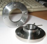
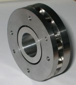
Why is the voice coil centred on the front plate instead of in the middle of the magnet?
What meterials are these plates/pole piece made of?
Are there any links explaining the basics of transducer design out there?
My questions are of the type:
Why is the voice coil centred on the front plate instead of in the middle of the magnet?
What meterials are these plates/pole piece made of?
Are there any links explaining the basics of transducer design out there?
Since this kind of info seems to be relatively undocumented for access to the DIYer, I thought I'd share my ongoing journey into transducer design:
Transducer Design Diary
No laughing please.
Transducer Design Diary
No laughing please.
Attachments
wow how sweet is that 😱
Got to make me an *** roll speaker, im sure that will confuse a few people
Got to make me an *** roll speaker, im sure that will confuse a few people
I'm not getting much midrange for a midrange, but understandable so considering every part is grazing something as it moves  . Getting loads of bass though.
I also added some elastic bands for suspension. I'll post a pic a bit later.
. Getting loads of bass though. I also added some elastic bands for suspension. I'll post a pic a bit later.
what kind of spider, cone, surround are you going to use. and are there any CAD-designs of your project? or is it going to be a scratch project?
i'd like to see the basket think, it's going to be interesting
are you doing any strength calculations or FEM for the basket ?
i'd like to see the basket
think, it's going to be interestingare you doing any strength calculations or FEM for the basket ?
You might find this helpful.
This is a great project idea, and that magnet assembly looks great already.
I've just whipped up an image below, I think the reason is that the pole piece is say, North, and the rest is South, I think. And the voice coil repells off the magnet flux...maybe someone could clarify
This is a great project idea, and that magnet assembly looks great already.
Why is the voice coil centred on the front plate instead of in the middle of the magnet?
I've just whipped up an image below, I think the reason is that the pole piece is say, North, and the rest is South, I think. And the voice coil repells off the magnet flux...maybe someone could clarify
Attachments
ksl,
So as to the kind of cone and surround. No idea. I'm currently thinking about the former/voice coil. And starting to think about the spider.
I'm trying to stay away from convention in the hope of finding alternative methods with different benefits. The last idea was to use springs in place of the spider. But after realising that the goal is to reset the voice coil to its natural position infintely quick, I can see why stiff paper spiders are used and why springs may be a bad idea.
I don't want to think too far ahead. At the moment i'm changing and evolving my design as I learn the theory or see the need too. And in this way the affect of each change is very clear.what kind of spider, cone, surround are you going to use
So as to the kind of cone and surround. No idea. I'm currently thinking about the former/voice coil. And starting to think about the spider.
I'm trying to stay away from convention in the hope of finding alternative methods with different benefits. The last idea was to use springs in place of the spider. But after realising that the goal is to reset the voice coil to its natural position infintely quick, I can see why stiff paper spiders are used and why springs may be a bad idea.
I used 3D Studio to design the magnet structure. But that's all so far.are there any CAD-designs of your project
Attachments
Thanks for the that Octupus. After some researching, I concluded that the magnetic circuit will harness the flux into a tiny air gap. I think that by using the top plate to create an air gap, the flux can be controlled into a narrow band which is better than using just a high magnet surface, especially as uniform flux is one of the goals. I though about using two ring magnets with opposing poles on the inner and outer ring surfaces. The magnets can then be the required height and there will be no loss in magnet strength from travelling through other metals. This was just one idea that I may try later. I don't know what the issues are with doing it this way. I certainly haven't seen this done before...I've just whipped up an image below, I think the reason is that the pole piece is say, North, and the rest is South, I think. And the voice coil repells off the magnet flux...maybe someone could clarify
Attachments

You can learn a bit about driver design from Martin Colloms' "High Performance Loudspeakers"
The motor is the easiest part.
The magnet provides field(it acts like a battery in a magnetic circuit) the top plate and pole piece concentrate it and put it where you want it. You want the field perpendicular to the coil windings at all times.
Force on the coil is B*L*i, where B is the magnetic strength, L is the length of wire in the gap and i is the current through the coil.
I have a spreadsheet I made for driver design which sums up a lot of what I have learned over the years...I'll see if I can find it for you.
Great that someone else is interested in transducer building too! See, i have not registered to this site long ago, and haven't been really looking for this kind of threads before.
I haven't seriously done any voice coils yet, just experimenting. But now there are two Monacor's sp-200x 8" drivers waiting on my shelf. Both of them have surrounds and whizzers gone bad. Would there be something that would dissolve the glue on the spider so that I could get it away in one piece? Acetone? I planned to use the magnet-vc-spider-cone system and make a frame from plywood etc. I would cut the cone smaller to 5" size, remove the whizzer and then coat the cone. I also have some 5" - 6" drivers lying around so their surrounds could be used.
I have also noticed that when you try to get the pole pieces together, the top snaps to unwanted position. I heard that this is solved in industry by magnetizing the magnet system after the pole pieces are all glued together. Of course this isn't possible to do home.
Here's a pic how I planned to do the "spider", if I some day have enough inspiration to do it...
spider system
I like your idea for the spider Otherwise. What material will you use for the 'lines'?
The idea of using corrogated stiff paper as a spider just doesn't sit well with me. So I'm looking at other possibilities. I'm sure there must be a reason why manufactures have settled on this as opposed to elastic/rubber or metal spring based solutions. Perhaps someone could enlighten me?
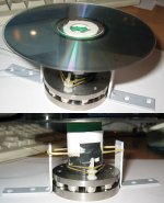
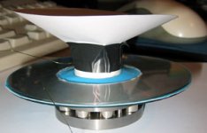
I tried a circular piece of rubber sandwiched between two CD's (with a larger diameter cutout) today. I cut it out of a rubber washing up glove, making sure that the inner hole was really small so that it would fit very tightly on the former. It worked really well. In fact, I'll probably use another rubber glove to make the cone surround.
The idea of using corrogated stiff paper as a spider just doesn't sit well with me. So I'm looking at other possibilities. I'm sure there must be a reason why manufactures have settled on this as opposed to elastic/rubber or metal spring based solutions. Perhaps someone could enlighten me?
I tried a circular piece of rubber sandwiched between two CD's (with a larger diameter cutout) today. I cut it out of a rubber washing up glove, making sure that the inner hole was really small so that it would fit very tightly on the former. It worked really well. In fact, I'll probably use another rubber glove to make the cone surround.
Attachments
I don't know yet what to use, but for example that line used in fishing or just something regular thin string. The good thing in the "line-spider" is that it would be very light system. Good for full-range driver's voice coil.
You might want to try doing the surround from PVC shower curtain. With suitable mold it should be easily shaped with hot air blower into half-roll surround.
You might want to try doing the surround from PVC shower curtain. With suitable mold it should be easily shaped with hot air blower into half-roll surround.

Thats how I started...Just an experiment to see what....
Then bang hooked...Noooooo£££££
It is a thrill when you get that first sound eh?
Then of course you HAVE to make it sound good
You are brave doing a moving coil design,loads of work for you there!![and £££]
If you want to see what your magnetic field is doing, download
Maxwell sv from
http:// www.ansoft.com/index.cfm
It is a fun program

Good luck 🙂
Setmenu
Cheers Setmenu. I had a quick play around with that software but I think it's going to take a while to figure it out.
I've also doanloaded FEMM which I'll have a play around with a bit later.
I've got some general questions about transducer design - assuming a midrange driver:
1) what size former? How does the diameter affect things?
2) what gauge wire? Is it simply a power handling/efficiency/weight tradeoff?
3) why a cone instead of a flat diaphram?
4) what's the job of a phase plug? Is it for cone shaped diaphrams only?
5) what are generally used/acceptable air gap sizes? Is 2-3mm too big?
6) How many voice coil layers should be wound?
7) What do you use to hold the voice coil to the former?
Quite a few there. But answeres to these basic questions are proving hard to find. Please help!
- Status
- Not open for further replies.
- Home
- Loudspeakers
- Multi-Way
- Diy dynamic driver