Hello all..
I'm working on a SMPS circuit to provide about 75W of power. Here are the basic details:
Vin range 12-16Vdc
Vout range 16.8V (10% regulation is fine)
Iout current 6A continuous
To increase the robustness I would LIKE to design to these specs:
Vin range 10-20Vdc
Vout range [same]
Iout current 8A continuous
Since the output currents are so great I am looking to use a synchronous SMPS circuit such as the LTC3780 (datasheet here), to reduce heat/power losses in the schottky catch diode (6A across Vfd of 0.63V would be over 3W of unwanted heat generation!).. (high efficiency is ultra critical since the ambient operating environment will already be QUITE hot, we can't afford a whole lot of additional heat generation.)
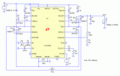
I'm using Linear Tech's LTSpice (SwitcherCAD) software and the defafult example circuit for this part ("3780.asc") and merely changing the part values (feedback R1=5K, R2=100K, inductor, etc) to meet my needs, and simulating the results for Vout ripple, inductor power dissipation, etc. I'm using the datasheet to calculate the appropriate component values..
I understand the basic theory of SMPS systems, and have designed a few low-power (< 10W) SMPS's in the past.. This is my first high-power design and I naturally have a few questions:
1) what problems are caused by using too SMALL an inductor value?
2) What problems are caused by using an inductor value much higher than recommended?
3) Typically power is calculated P=IV, but can also be written P=IIR. And in the case of the switching inductor, these equations do not produce the same result. In the phase when the inductor is switched to ground to increase the magnetic field (e.g. ramp up the current through the inductor), the voltage drop across the inductor is the full rail value (minus minimal MOSFET RDSon losses), such that when using P=IV, you get pulses of 10A * 12V (in case of a 10A load at 12Vin) which calculates to 120W. However when using IIR in that same situation where R is the DCRmax of the inductor (6.1mOhm in the case of the CoilCraft DO5010H-222), the equation yields 10A * 10A * 0.0061 = 0.61W... A substantially different result! So what do I use for my calculations?
thanks so much for all y'all's help!
..dane
ps-- I've attached a copy of the example circuit from the LTspice application for those curious but don't already have the application installed...
Attachments
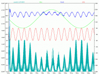
By the way -- you'll notice the input voltage is a sine wave, as is the output current drain.. This is the quick-and-dirty way that I simulate a variety of scenarios.. varying the load current at a faster rate and varying the input voltage at a slower rate and watch how the circuit responds..
Attached is a plot of the simulation results so far..
..dane
Attached is a plot of the simulation results so far..
..dane
Attachments
Hmm... no responses yet?
What I found interesting is that my efficiency is still "low" (83-85%) even when using synchronous SMPS topology... However, if I convert the supply to a boost-only SMPS by removing Q1, Q4, and D3 (and effectively 'shorting' across Q1's old drain and source locations), the efficiency shoots up to 96% or so, which tells me most of my inefficiencies lie in the MOSFET switching and likely RDSon characteristics..
The problem that arises with a boost-only configuration, however, is the massive inrush current to charge the output capacitors to the input line voltage. I'd like to know some practical ideas to help reduce the inrush current?
thanks!
..dane
You cannot use P=IV formula, because they are not in phase, P=IVcos(phi) is right, phi being presumably 90 degrees for that sort of designs (inductor phase shift).
Concerning inductor value you must take several things into account.
When too small, than you'll have high di/dt, high peak current and therefore low duty cykle for the said output current. Too big will very early force continous mode, hope I didn't oversimplify things here, but you seem to understand those things pretty well.
P.S. For boost-only the standard solution is an input to output diode
The inductor value is selected based on how much ripple current you will allow. The data sheet provides guidance on this.
The power loss in an inductor is Irms^2*R, but you need to know the RMS current which is not the same as the average or peak current. The power loss in an inductor is not I*V.
The power loss in an inductor is Irms^2*R, but you need to know the RMS current which is not the same as the average or peak current. The power loss in an inductor is not I*V.
darkfenriz said:You cannot use P=IV formula, because they are not in phase, P=IVcos(phi) is right, phi being presumably 90 degrees for that sort of designs (inductor phase shift).
Concerning inductor value you must take several things into account.
When too small, than you'll have high di/dt, high peak current and therefore low duty cykle for the said output current. Too big will very early force continous mode, hope I didn't oversimplify things here, but you seem to understand those things pretty well.
P.S. For boost-only the standard solution is an input to output diode
boost-only with a catch diode causes too much loss of efficiency (talking about multiple output amps here), which is why I am going with the LTC3780 in boost-only mode (removing the mosfets used for buck mode) ...
and regarding power calculation I am figuring that a quick-and-dirty power estimation through the inductor would the be the I^2 * R where I is the current through the inductor and R is the resistance (not inductance) of the inductor..
sawreyrw said:The inductor value is selected based on how much ripple current you will allow. The data sheet provides guidance on this.
The power loss in an inductor is Irms^2*R, but you need to know the RMS current which is not the same as the average or peak current. The power loss in an inductor is not I*V.
yes, through some simulation I see that lower values work fine so long as I can support the duty cycle and peak currents (ltc3780 provides controls for peak currents, so that helps), but causes higher output ripple.. I'm using some higher value parts now but can't go too high due to the current requirements..
thanks guys!
..dane
darkfenriz said:I meant input voltage to output voltage diode, which limits inrush current flowing via inductor and often causing problems with saturation at startup...
Hmm... if you mean basically a diode shunting around the SMPS from Vin to Vout (since we're in boost mode only now), then I can see how it could fix inrush through the switching inductor, but still causes a mass of inrush current through the diode, which will probably not do too well over time either due to the high potential inrush currents (40A or greater)...
..dane
- Status
- This old topic is closed. If you want to reopen this topic, contact a moderator using the "Report Post" button.
- Home
- Amplifiers
- Power Supplies
- Questions when designing a syncrhonous SMPS (75W)

