Attachments


congratulations on the excellent project which the values of bias adjustment to 60ma. I can change the value of
R109 = 470r for trim-pot for 1k to set off-set.
R109 = 470r for trim-pot for 1k to set off-set.
Attachments

The first circuit is simply Musical Fidelity's A1 power amplifier redrawn, without component values.
The "Chet Baker" Amp is a Rotel clone with a slightly different output stage - the graphics used for the schematic, style of compensation, plus the choice of transistors is identical to many Rotel service manuals.
The "Chet Baker" Amp is a Rotel clone with a slightly different output stage - the graphics used for the schematic, style of compensation, plus the choice of transistors is identical to many Rotel service manuals.
The Chet Baker schematic has a Bryston style output, which can be tricky to keep stable.
One thing the 0.22 resistors in the collectors of the CFP output devices serve no purpose. I think they should be moved to the emitter side.
I'm interested to hear if it works
One thing the 0.22 resistors in the collectors of the CFP output devices serve no purpose. I think they should be moved to the emitter side.
I'm interested to hear if it works
Thanks Symon
can you post a Bryston style output schematic example?
see the source of this idea:
http://www.esafono.it/ccc.pdf
can you post a Bryston style output schematic example?
see the source of this idea:
http://www.esafono.it/ccc.pdf
Attachments

there used to be a technical description on hte bryston web site, but can't find it right now.
take a look around the site.
Bryston Technical
this is the schematic of a Bryson amplifer
Bryston Schematic
You can also find discussion on Bryston amplifiers here on DIYAudio ..
take a look around the site.
Bryston Technical
this is the schematic of a Bryson amplifer
Bryston Schematic
You can also find discussion on Bryston amplifiers here on DIYAudio ..
In the original project could not a good result
modified some parts in the scheme to operate the simulator see the components changed:
R103 and R113 = 47k
R115 connecting a capacitor of 220uf to the ground.
R127 = 2k
Vr103 = 1k
R125 = 1k
q107 put capacitor 22pf of B / C.
modified some parts in the scheme to operate the simulator see the components changed:
R103 and R113 = 47k
R115 connecting a capacitor of 220uf to the ground.
R127 = 2k
Vr103 = 1k
R125 = 1k
q107 put capacitor 22pf of B / C.


Beto said:In the original project could not a good result
modified some parts in the scheme to operate the simulator see the components changed:
R103 and R113 = 47k
R115 connecting a capacitor of 220uf to the ground.
R127 = 2k
Vr103 = 1k
R125 = 1k
q107 put capacitor 22pf of B / C.
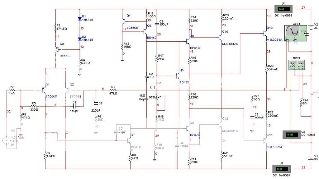
Stee the simulator seemed ok but I want good opinion of other friends of the forum here because the simulation was done with some changes and to make sure the quality of the amplifier will have to mount the project.
simulation found in the high THD.
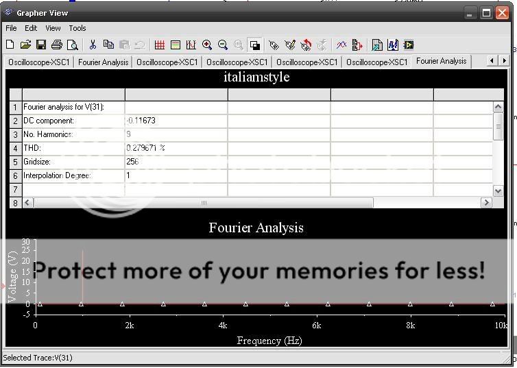
simulation found in the high THD.


STEE the design of the card did not because I am not very good at drawing card. the design and simple to assemble a 4,256 points in placaProtoboard Islands 10x30cm.


R20 and R21 in the emitter because the problems in the simulation showed bias when in ultilizado collector.
may be some bug in the simulator and not 100%.
Mounting the project in practice show the reality of the project
may be some bug in the simulator and not 100%.
Mounting the project in practice show the reality of the project
Beto said:
Beto, your schematic looks off. Look at Q13's base. Shouldn't this be connected at Q8's emitter?
- keantoken
- Status
- Not open for further replies.
- Home
- Amplifiers
- Solid State
- italian style