i know im new at this so hopefully this will be easy for someone to help with.
i am working on a MTX 3401.
there are 2 independant circut boards one for the amp stuff and a seperate one that houses the gains and adjustments. its the adjustment board im having problems with
it looks like a small silver barrel and has the numbers "10 16s 4f8" on the top of it, i put power to the amp and this part actually exploded and shot across the room. is this normal? what is this thing and where do i get a new one?
what causes this to fail? should i be looking for another problem?
i cant measure it, all that is left on the PCB is just 2 tabs, it seriously dynamited in a big loud blaze of glory. do you think i can just guess and use the specs you recomended?
yes the transistors were bolted to the heatsink. this little capacitor was on a completely seperate board within the same amp.
what will cause the "regulator" to cause this to happen? should i check that it is ok before putting in a new capacitor?
yes the transistors were bolted to the heatsink. this little capacitor was on a completely seperate board within the same amp.
what will cause the "regulator" to cause this to happen? should i check that it is ok before putting in a new capacitor?
Before you replace it, you need to measure the DC voltage from the regulators. I don't have any information on this particular amp. Can you post a few photos of the internals?
If there are other caps with the same markings, you can measure them. The most important measurement is the pad size/spacing. The height isn't likely to be a problem.
When the regulator fails, it often sends full rail voltage to the regulated 15v circuit. This will cause the caps to explode. It can also cause extensive damage to other components. The following thread dealt with a regulator failure in an MTX 7801.
http://www.diyaudio.com/forums/showthread.php?s=&threadid=119800&highlight=
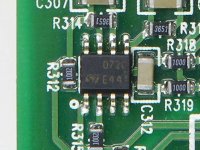
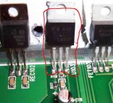
This is a different amp but yours should be similar. The black, 8 legged device in the photo is an op-amp. There should be one in your amp near the RCA jacks. The lower left (near the white circle) is pin 1, the lower right is pin 4. The upper left is pin 8. On pin 4 you should have approximately -15v. On pin 8, you should have approximately +15v.
Attachments
it is even the same part number as mine. the voltages i measured line up with my picture. i think its safe to say that the regulator has failed. i just put the neg lead on the feed to the amp and then stabbed the leads with the pos lead
-0 -48
-45 0
-45 -45
-46 -46
-0 -48
-45 0
-45 -45
-46 -46
Attachments
yes for sure i would like to atleast attempt to repair this thing. so far on my parts list is this op-amp number "072c e441" and a 10uF 16v SMD capacitor.
is there anything else i should check before ordering?
yes my ground lead from the voltmeter was attached to the main ground lead on the amp.
is there anything else i should check before ordering?
yes my ground lead from the voltmeter was attached to the main ground lead on the amp.
Before I can help you through this repair, you'll need to send me approximately 10 good quality photos of the various sections of the amp so I can see how the amp's laid out. The photos will need to be good enough so that I can read the numbers off of the SMD components.
If you read through the 7801 repair (you should have read every page of it), you should realize that this process may take a month or more and there's no guarantee that we can get it repaired. If you simply want it repaired, you should pay to have it repaired (it will likely be less expensive in the long run). If you want to go through this as a way to learn more about amplifiers, I'm willing to try to help. Expect to spend 20+ hours working on the amp with no guarantee that it will be repairable via the forum.
If you want to continue, send me the photos.
babin_perry@yahoo.com
The op-amp and capacitor are likely only the tip of the iceberg. Before you order anything, we need to do more troubleshooting.
There are several 10 ohm resistors (10R0) near the TL074Cs that are burned. That probably means the 074 is defective. Check the resistors marked 10R0 near each of the following ICs
8 pin near large cap near the corner of the board
8 pin near the RCAs
all TL072/74 ICs on the preamp board
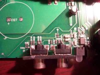
Pull the clamps off of the regulators (no power applied to the amp) and get the numbers off of them. U103 and the one directly across the heatsink are the regulators. They are probably an LM137 and an LM337. You'll need to replace both of them.
8 pin near large cap near the corner of the board
8 pin near the RCAs
all TL072/74 ICs on the preamp board
Pull the clamps off of the regulators (no power applied to the amp) and get the numbers off of them. U103 and the one directly across the heatsink are the regulators. They are probably an LM137 and an LM337. You'll need to replace both of them.
i did my best to check the resistors and i only found the 2 that are bad near the RCA inputs. the resistors that are marked 10r0 measure to 10 ohms. and i cant find any others with obvious burns in the center
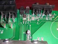
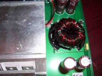
i found quite a bit of damage to the smaller board but i figure i will wait for that one till i get the main board figured out
i found quite a bit of damage to the smaller board but i figure i will wait for that one till i get the main board figured out
Attachments
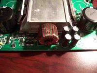
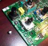
The regulators are 2 of the the black devices with metal tabs that are clamped to the heatsink. One is marked U103. The other should be directly across from U103 clamped to the other side of the heatsink. The component with the round core parallel to the surface of the board is the power transformer. The one on the other end is the output filter inductor.
The 10 ohm resistors are probably 0805 (0.08" x 0.05").
The 10 ohm resistors are probably 0805 (0.08" x 0.05").
- Status
- This old topic is closed. If you want to reopen this topic, contact a moderator using the "Report Post" button.
- Home
- General Interest
- Car Audio
- what is this?