Hello,
I've been a long time reader but seldom poster on this site. But I use it for reference and ideas alot, there's definatially alot of bright individuals here. Usually I can find my answers using the search, but no direct answer this time lots related to home amp grounding schemes but not car.
So my problem is: Ground loop in a 4 channel gainclone.
Here's a little about the amp, power supply is a smps with 28.5v rails, good amount of filtering and isolated ground (relative to the rest of the car) there are 4 lm3886's in a fairly standard non-inverting setup, each pair of input rca's shares a common ground (that's how the rca block is built) and there is a wire from that point to the star ground) now when I connect 2 rca inputs (front or rear) there is no noise at all, the music is wonderful, clear, detailed, powerful, theres no turn on/off noise and no hum. Now the problem starts when I connect the 2nd set of rca cables (these are both coming from an alpine CDA-9813, using the front/rear rca outputs) I get loud nasty noise, from all 4 channels. Now here's one other piece of important info, the two rca cables are different lengths and brands/styles. Now my first question is would identical rca cables potentially solve this problem? IE if the ground path/impedance from the F/R rca's at the head unit were identical to the amp would/could this solve it?
Or do I need to look at changing the ground arrangement within the amp itself? I've built many 2 channel car gainclones and never had a noise issue with any of them, but this is my first 4 channel.
I have some closeups of the amp at home and can post them later tonight if that might help. There's a few other details that might come out aswell due to the layout/wiring that someone might pick out as a red flag. I've always been careful, but not critical of my grounding methods and never had a problem, that might have caused this.
I'm thinking, try 1R (one ohm) to 10R between your RCA block and the star ground. Otherwise, just replace that RCA block with something that makes individual lines to each of the 4 amplifiers.
This is really just a guess.") Anyway, I think that you don't want your input circuit ground to become the path of least resistance, because, if it is, then both audio signal *and* power will try to run through it.
Anyway, I think that you don't want your input circuit ground to become the path of least resistance, because, if it is, then both audio signal *and* power will try to run through it.
EDIT: Somewhat less issue is that one amplifier's input circuit could become an attractive grounding point for another amplifier's power circuit. So, do try to isolate their input circuits.
This is really just a guess.
Anyway, I think that you don't want your input circuit ground to become the path of least resistance, because, if it is, then both audio signal *and* power will try to run through it.EDIT: Somewhat less issue is that one amplifier's input circuit could become an attractive grounding point for another amplifier's power circuit. So, do try to isolate their input circuits.
4-channel gainclone with hum issue. that sounds awfully familiar
Solution:
http://www.diyaudio.com/forums/showthread.php?s=&threadid=118735
Solution:
http://www.diyaudio.com/forums/showthread.php?s=&threadid=118735
rwaudio said:Now my first question is would identical rca cables potentially solve this problem? IE if the ground path/impedance from the F/R rca's at the head unit were identical to the amp would/could this solve it?
I have some closeups of the amp at home and can post them later tonight if that might help. There's a few other details that might come out aswell due to the layout/wiring that someone might pick out as a red flag.
Identical rca cables won't solve your problem. It definitely sounds like you have a ground loop. Feel free to post pictures of the amp and also any schematics of the power supply and how you have it all wired up.
Hi! I am actually building an 8-channel car amp based on LM3886 PA100s + a BPA200 for the subwoofer channel. I have that many channels to support the 5.1 Dolby Digital of my Alpine DSP + 2 spare channels.
I went through ground loop testing on a similar setup/amplifier (my original 2-channel proof-of-concept prototype) and searched for solutions in the DIYAudio.com forum also.
People suggested ensuring that the power ground is isolated (as opposed to using a ground loop isolator on the RCAs, which sucks for fidelity).
I now have ZERO ground loop noise since isolating the SMPS ground from car ground. Same solution for my tube preamplifier.
Are you ABSOLUTELY sure you have an isolated ground? Definitely sounds like you have a ground loop due to interconnected grounds somewhere.
If you remove that it shouldn't really be possible to have a ground loop, if you think about the ground loop concept.
Good luck! I'd love to compare amplifier notes also!
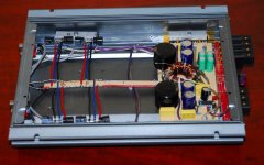
here's a picture of the amp.
At the moment I'm running all four channels off of one set of rca's and everything is perfect, it's only when two sets of rca's are used the noise is there(there's also the posibility of the 2nd rca being bad, I'll have to test that)
as you can see each "pair" front and rear have their own signal star ground, could that be part of the problem? This was done to keep the layout clean and easy to setup.
And MartyM the output ground of the smps is completely isolated from the cars ground. From what I can tel the ground loop is between the head unit and amp, and the ground difference is caused by the two ground paths of the two types of rca cables. But how do I fix it?
Attachments
Well, basically assuming "all is well" in the amplifier I would start using trial and error to eliminate the source.
Note: I'm not quite sure I understand how you mean exactly regarding the star grounds of the RCA connections in the amp. But anyway...
I would start with eliminating the ground of the head unit to chassis and instead connect that (with a decent sized wire) directly to the ground terminal of the amplifier and eliminate one variable.
Then when everything is turned on, start using small wire with bare ends to connect the RCA shields to (1st pair to second pair) each other, then RCA sheilds to amp ground terminal, then to the head unit chassis, then etc...
In my experience usually you'll end up (eventually, though not easy) find what general conductor is carrying the ground loop.
what happened when you measured continuity from the RCA shield conductors to chassis ground for both front/rear RCAs?
And, have you tried usually only one pair of RCAs at a time, but connect those to all 4 inputs to the amp using Y cables in order to see if it happens?
Those are just suggestions...
Hey MartyM thanks for the reply.
At the moment I have all 4 channels running off one set of rca's (instead of using Y adapters I just desoldered/resoldered where the rear channels get their signal from) with all 4 channels getting signal from the front rca's there is no noise at all.
And before when i used one rca cable on either the front or rear channels there was no noise.
I will have to try your wire idea though and see if I can track down exactly where the noise is coming from, as well as regrounding the head unit at the amp.
Well good luck to you. I ended up learning about using a small, thin wire as a jumper to connect various grounds (RCA shield, amp ground, car (@ stereo) chassis ground, batt. - terminal) when first learned about the concept of ground loops (but not soon enough!) years ago.
I also had some luck occasionally connecting all 4 RCA shields together on some 4 channel amplifiers. I recall 2 cases where that neutralized the ground loop. (Was on a lower end Clarion amp, etc.). I kept connecting grounds by trial and error until ultimately the culprit was discovered.
But it takes time. Too many shops simply throw a (low cost) ground loop isolator on the RCAs and call it "fixed" although it hurts sound quality unless you have the ones that Perry Babin posts about on this site.
Your situation got me to thinking about how I need to test my amp again since now it contains multiple SMPS supplies instead of only one.
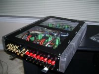
Also I think I've learned the hard way to do like you and save a lot of grief, time, and money by fitting the chip amps into the amplifier case, instead of the other way around!
Did you have any issues with the gain of your gainclones? If so, what Rf feedback resistors did you find best (for your head unit)?
At any rate here's my first car amp project, almost finished:
Marty
I also had some luck occasionally connecting all 4 RCA shields together on some 4 channel amplifiers. I recall 2 cases where that neutralized the ground loop. (Was on a lower end Clarion amp, etc.). I kept connecting grounds by trial and error until ultimately the culprit was discovered.
But it takes time. Too many shops simply throw a (low cost) ground loop isolator on the RCAs and call it "fixed" although it hurts sound quality unless you have the ones that Perry Babin posts about on this site.
Your situation got me to thinking about how I need to test my amp again since now it contains multiple SMPS supplies instead of only one.
Also I think I've learned the hard way to do like you and save a lot of grief, time, and money by fitting the chip amps into the amplifier case, instead of the other way around!
Did you have any issues with the gain of your gainclones? If so, what Rf feedback resistors did you find best (for your head unit)?
At any rate here's my first car amp project, almost finished:
Marty
Attachments
That's a good point!
Yes, if the input circuit has a really thin wire, that makes its ground to be less attractive to power.
Also possible, four resistors (from 1R to 10R series). These go from the RCA panel's common ground, and make that into 4 seperate grounds for your 4 amps.
Either method is pretty similar.
However, we forgot to mention to use a really sturdy thick ground for your power ground. That ground, which doesn't carry audio, needs to be the most attractive spot for weird little buzzes, blipz, hums, snorts, growls--make 'em go down the power ground instead of your audio ground.
Also forgot to mention the source. Maybe the problem isn't in the amplifier? You know how one amplifier could possibly have its audio ground become power ground by accident (all that blather above). Well, exactly the same thing can happen to your source. Source equipment usually contains op amps. Usually small op amps, like most sources, like 1R (series) at the output side, and if this is on the ground side, it can't ground loop that way.
The simplest thing?
Does the amplifier have a load on its input? = does the source have a load to drive? If not, arrange a 20k load per each channel. That might be 4 of 20k resistors, from hot to ground, on all 4 RCA on that RCA panel. This will simulate 4 potentiometers and it will give the source a load to drive.
These are ideas to try, and not firm recommendations. Just use whatever happens to work.
Hi MartyM that amp looks good, the casing must have taken awhile, looks like you built it from scratch. I have a few dead amps laying around so it was easiest to gut them and use a few of the good parts in my amp (ie power/ground/speaker terminals the toroid and some caps) I'd like to see more pictures of your amp and the rough design. I should have some time tonight to do some playing so I'll try the ideas that have been posted. I really need to get this running off seperate rca's because using the time alignment right now just destroys the sound stage because it controls ALL left/right speakers with the front outs.
I don't recall what I used for the gain setting resistors, I just know I had to lower it from what I used on my home amp, I can measure them next time I have it on the bench, but I have an alpine deck with 4v preout and normal listening is at about half volume and loud is 3/4+ but I've never gotten upto full vol on the deck. So I think it's a good match.
danielwritesbac, I've heard many people say use small wire for the signal grounds, I'm gonna try that now, I have 18awg at the moment which is what the whole amp uses for power/ground to each lm3886, so signal ground would be just as attractive because it's also 18awg.
And yes, even though I didn't use gain controls (because it's made to work with my deck) I have 47k signal to ground resistors so the deck should see that as the load at the amp input.
Atleast I have some things to try, thanks guys. I'll keep posting what does and doesn't work in my situation.
on a side note though, I've thought of trying something that I use when building headphone amps, the headphone return (ground) is isolated from the signal ground by a buffer (buf634 or similar or even just an opamp at unity gain) it's not exactly the same application but the objective is the same in both, completely isolate the grounds while keeping them at the same level.
- Status
- This old topic is closed. If you want to reopen this topic, contact a moderator using the "Report Post" button.
- Home
- Amplifiers
- Chip Amps
- Grounding scheme in a Car Audio Gainclone???