In the 'permanent' spice thread, someone suggests a 'basic spice' course or wiki. Does something like this exist here?
For the moment, I have a RC-loaded circuit the distorts heavily where I thought it wouldn't *and* one that behaves well where I thought it shouldn't work [neat|at all].
I guess I'm not the only one...
What I have in mind are some kind of 'standard treatments' in very basic circuits (high and low pass, 1-Q-followers or -gain blocks and the like).
Rüdiger
See http://newton.ex.ac.uk/teaching/CDHW/Electronics2/userguide/
There are some examples, I think in one of the appendices.
There are some examples, I think in one of the appendices.
May I present a problem which should lead us to some basic RC-treatments?
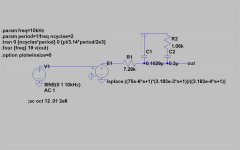
Beneath is a riaa network(, fed by an ideal sine wave and inversed and 'gained' by an ideal inverter/amplifier.
A distortion measurement as displayed gives me a THD of 3.56%!
This method is given by Klaus (KSTR here) and gives reasonable numbers for a bunch of well documented circuits I tried.
As I think, that an 'ideal' phono pre shouldn't distort that much, there should be mistakes in this setup.
Which?
Rüdiger
Attachments
A reported "problem", see
http://www.diyaudio.com/forums/showthread.php?postid=1246419#post1246419
And the user manual reads:
"The transfer function of this circuit element is specified by its Laplace transform. The Laplace transform must be a function of s. The frequency response at frequency f is found by substituting s with sqrt(-1)*2*pi*f. The time-domain behavior is found from the impulse response, which is found from the Fourier transform of the frequency-domain response. LTspice must guess an appropriate frequency range and resolution. The response must drop at high frequencies or an error is reported. It is recommended that the LTspice first be allowed to make a guess at this and then check the accuracy by reducing reltol or explicitly setting nfft and window. The reciprocal of the value of window is the frequency resolution. The value of nfft times this resolution is the highest frequency considered."
In reality (within the simming context), you don't have any distortion in the time domain, because both the laplace and the passive components are LTI (linear time-invariant). One can model nonlinear caps and resistors, though.
- Klaus
Hi Klaus,
thanks for your answer.
I have to admit, though, that I'm completly lost here.
Are you saying that I shouldn't get the THD-numbers I quoted? Or that I should ignore them? Then the word 'problem' shouldn't go with quotes because any analog filter circuits can't easily be tweaked.
thanks,
Rüdiger
thanks for your answer.
I have to admit, though, that I'm completly lost here.
Are you saying that I shouldn't get the THD-numbers I quoted? Or that I should ignore them? Then the word 'problem' shouldn't go with quotes because any analog filter circuits can't easily be tweaked.
thanks,
Rüdiger
There should be no THD.
Your problem is that you have not allowed any settling time, so the output waveform is distorted by the initial charging transients.
Accurate simulations require the use of extra start time parameter in the .tran card.
Your problem is that you have not allowed any settling time, so the output waveform is distorted by the initial charging transients.
Accurate simulations require the use of extra start time parameter in the .tran card.
Rüdiger,
Yes, you should get a straight zero for THD, because all elements are linear with regard to voltage and current. More precisly, you get the generator's intrinsic distortion multiplied with gain error at the harmonic frequencies. Say you input is 1kHz with a -90dB H2 component and your frequency response error is -1dB at 1kHz -3dB at 2kHz, H2 would come out as -92dB. But the generator distortion is really low, <= -160dB when using a small max timestep.
The errors you see come from the problems of doing the Laplace transform in the time domain, in LTSpice. Seems that one can't use it at all or has to know all the guru tweaks to get reasonable results (I don't).
Dad also raised a point... so try that first, let it run for like 20 cycles and then .four the last ot these (which it does by default).
- Klaus
Well, ok, seems I should read the error log as such as well...
"Frequency response of Laplace device "E1" does not roll-off fast enoughLaplace source: E1
WARNING: This Laplace expression needs an additional delay of 23.2µs to not violate causality.
Freq Domain: peak @ 0Hz BW=0Hz cutoff @ 0Hz
resolution: 250Hz nfft=16384
Time Domain: window=0.00196045s resolution: 2.44141e-007s
Second Compression Ratio=422.632
"
I altered the tran command to
.tran 0 {10*(ncycles*period)} 0 {pi/3.14*period/2e3}
this gives me a thd of .055%.
With
.tran 0 {20*(ncycles*period)} 0 {pi/3.14*period/2e3}
I get 0.022%.
The command
.tran 0 {100*(ncycles*period)} {99*(ncycles*period)} {pi/3.14*period/2e3}
gives .000134%
the same as
.tran 0 {100*(ncycles*period)} 0 {pi/3.14*period/2e3} to check if the simulator really choses the last cycle(s).
So, if one has the time (ran ~ 10minutes on my 2.4 GHz (or the like) PC it is at least usable to see if your circuit develops issues with one's RC- network.
Thanks!
Rüdiger
For most work, you don't need to use a simulation step as short as period/2e3 - for most circuits a something like period/100 will do, and goes 20 times faster.
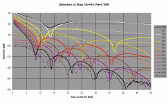
THD vs Frequency
That's too complex for us beginners!
Go and read the authorities in that other thread.
That's too complex for us beginners!
Go and read the authorities in that other thread.
Not directly from the program... but you can .step the test frequency and past the output from the error log into a little spreadsheet that can plot whatever you like.aparatusonitus said:Can LTSwCAD plot THD vs freq., and how to do that if it can?
I did similar similar stuff (stepping a voltage in the example) and you can make nice plots of distortion vs. xyz.
- Klaus
Attachments
I have a new beginners problem.
The IRF9610 and it's cousins seem only obtainable as a .subckt.
So I Followed the instructions of the help file, i.e. creating a file containing the subcircuit, .include it (that worked so far) and then change the reference designator into 'X', and enter new value for the particular part (XIRF9610 in this case).
But, I get an error message : 'Can't find definition of model xirf9610'
What am I missing?
Rüdiger
Value should be IRF910, not XIRF910, also make shure that subcircuit text .subckt IRF9610.... is not in the first line in IRF910.sub file, just move all subcircuit text line below top.
KSTR said:Not directly from the program... but you can .step the test frequency and past the output from the error log into a little spreadsheet that can plot whatever you like.
Thx for the tip Klaus, will try that.
that is not the case here. Without the X, nothing is found. Which is no wonder, because the file starts with
*IRF9610 MCE 4-2-96
*200V 1.8A 3 ohms HEXFET pkg:TO-220 2,1,3
.SUBCKT XIRF9610 10 20 40 40
But, addtionally to what's written in the help file, you also have to open the component attribute editor and fill in the field 'value2' the value 'xirf9610' once more. Now I have at least reasonable behaviour of the part.
Why on earth I first have to ask a question to others to find the answer for myself?
Sorry to take your time,
Rüdiger
Rüdiger,
the problem is that the .asy (=symbol) file for NMOS can reference only to a true .MODEL, not to a .SUBCKT type of model.
I solved that by copying all the symbols NMOS, PMOS, NJFT, PJFT, NPN, PNP to files with prefix X (like XNMOS.asy) and change the line (here for the NMOS):
SYMATTR Prefix M
to
SYMATTR Prefix X
Then you can .inc (or .lib) the subcircuit and rename the value of the symbol to IRF610...
I wonder about this "not in the first line stuff", it is simply not true for me (that is, it does not matter).
- Klaus
oops,
something is still wrong. the source is at 31mA in my case, while the drain has 62mA, the gate some tens of pA ???
The Vgs is slightly wrong with 3.25V instead of the 4.4V I get in reality.
Rüdiger
EDIT: I made a new file xpmos.asy, but I still have to change the prefix and value2 manually in the component attribut editor.
Rüdiger
- Status
- Not open for further replies.
- Home
- Amplifiers
- Solid State
- Spice for beginners?