
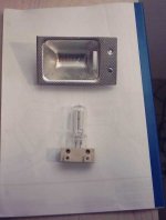
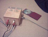
till said:Yes, but lighning ZEN is aestetically the absolutely best, and what would be a better use for these: ?
anything to change in feedbackloop?
Yeah, but NP uses another kind of lamp!
It depends on the kind of lamp look at the Manufactum Catalog
for vintage carbon lamps! (Kohlefaden gibts dort)
http://www.manufactum.de/mhp1/cgi-b...496560740540174334&pT=60848&pnrJava=1&pstrLZ=
Uli
Hey, i´m student. The TAD Speaker project keeps me low on moneys for some more month. A ZEN light with those lamps must look very pretty. But i would need 12 - 24 pieces for a twochannel amp. 17€ for 115W at 220V => 200 - 400 Euro for lightbulbs. I´ll try my halogen 1000W one each channel first. and i don´t need much more than some 100mW out of the amp with the TAD´s!
That is true!uli said:Yeah, but NP uses another kind of lamp!
It depends on the kind of lamp look at the Manufactum Catalog
for vintage carbon lamps! (Kohlefaden gibts dort)
http://www.manufactum.de/mhp1/cgi-b...496560740540174334&pT=60848&pnrJava=1&pstrLZ=Uli
If you read the Zenlite PDF carefully
you'll see Nelson Pass put in a lot of hard work/search,
before he found some lightbulbs that could
come close to give a satisfactory result in an audio amplifier.
Read the PDF once more!
/halo - has good memory still - often only reads once.
Well kept brainfunction of this old man

The Zen Lite should be used with the High / Low Pass http://www.diyaudio.com/forums/showthread.php?s=&postid=155394#post155394
driving TAD2001 with my horns http://www.diyaudio.com/forums/showthread.php?postid=96329#post96329
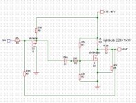
I´m still not sure about the schematic. I don´t want to build it exactly like the original Zen Lite. I don´t have a large 4mH inductor, i don´t want a turn on thump protection circuit. I don´t need low frequency from the amp as the TD2001 should be used above something between 500 and 1000Hz. So i think some capacitors could be smaller -- what means i can use higher quality (film instead of elko) I don´t have ZVP3310 so i have to use IRFP9610. The amp will have no powersupply - only a connector for an external powersupply 2m away. Mr. Pass, could you please critically comment this schematic?
driving TAD2001 with my horns http://www.diyaudio.com/forums/showthread.php?postid=96329#post96329
I´m still not sure about the schematic. I don´t want to build it exactly like the original Zen Lite. I don´t have a large 4mH inductor, i don´t want a turn on thump protection circuit. I don´t need low frequency from the amp as the TD2001 should be used above something between 500 and 1000Hz. So i think some capacitors could be smaller -- what means i can use higher quality (film instead of elko) I don´t have ZVP3310 so i have to use IRFP9610. The amp will have no powersupply - only a connector for an external powersupply 2m away. Mr. Pass, could you please critically comment this schematic?
Attachments
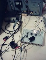
I have it running, but without the 9610 yet.
One more question:
from the article
What are more sensitive speakers? TL1601a and TD2001 are more sensitive or not? i have no turn on delay circuit now. Would a powers supply that turns on very slowly be an alternative? a regulator powersupply with a delay?
One more question:
from the article
The circuit of Figure 5 has a substantial turn-on thump as the voltage across the MOSFET goes from 0 to 15 volts, and some of your more sensitive speakers might take offense. Figure 14 shows a simple turn-on delay circuit which will short the output of the amp to ground for a few seconds.
What are more sensitive speakers? TL1601a and TD2001 are more sensitive or not? i have no turn on delay circuit now. Would a powers supply that turns on very slowly be an alternative? a regulator powersupply with a delay?
I don´t know how the Zen Lite behaves switching it off just though I mention this.Yes, this was what i thought of. But turn off thumb? if i turn off it goes slowly silent and distorted but no thumb.
Marcello who scaled the Zen amp for the use with headphones experienced a turn off thump and recommended a circuit that shorts the ouput during startup and switch off as well to avoid that.
In that case the regulator of the ZenV3 wouldn´t be sufficient.
But I think I´ll try anyway ;-)
Cheers
Jens
You are going to have some difficulty with this circuit with R1
looking at the top of the light bulb. R1 and R2 are there to
set the DC operating point for the Mosfet, but to do this they
need to see the Drain voltage of the Mosfet, and your circuit
only gives the supply. At the very least, make R2 a
potentiometer.
Note that the impedance of R1 and R2 are quite high compared
to the source impedance. As such, they don't contribute much
in the way of feedback at AC frequencies - they simply set the
bias point.
Thank You very much. If i connect R1 to drain, shall i make R2 a potentiometer too? Should it be adjusted to 1/2 V+ at drain or to 15V?
Is the circuit diagram right so?
Would values for C1 and C2 be ok in case the amp is used as high frequency amp for TD2001 and driven by the coming High / Low Pass Xover or do they need to be larger?
V+ is only 35V at the moment because my bench supply don´t delivers more. I think a final PS will be 45 - 50 V so.
- Status
- This old topic is closed. If you want to reopen this topic, contact a moderator using the "Report Post" button.
- Home
- Amplifiers
- Pass Labs
- ZEN amp question