My JLTi gainclone doesn't work. Everything powers up, nothing gets hot, but there's no sound output. The PSU for the lot is ±20vDC (Yes, it's low, but the only affordable solution I found)
The tube itself actually outputs something(at a much lower gain than directly taking the input)
The problem is, there is no sound at all in the speakers output. No pop when starting, no hissing, simply nothing.
Is there any place I should look at? I modified the schematic as per the LM3886 datasheet, V+ gets to destination, V- as well, Vin+ and - too. It's pretty strange. By the way, I have a 6DJ8 tube.
I just tried connecting my source(portable radio, adjustable volume) directly to Vin- through a DC blocking cap, and I still get nothing. The only time I get a thump on startup is if I unplug the -20v line. I get scratching on the sound output while I plug/unplug the -20v line. Speaker is plugged on LM3886's pin 3, v- on pin 4, v+ on pin 1, pin 7 to ground, vin+/- pins 9/10.
One thing, I left the mute pin floating, is this a right thing to do?
One thing, I left the mute pin floating, is this a right thing to do?
DragonMaster said:I just tried connecting my source(portable radio, adjustable volume) directly to Vin- through a DC blocking cap, and I still get nothing. The only time I get a thump on startup is if I unplug the -20v line. I get scratching on the sound output while I plug/unplug the -20v line. Speaker is plugged on LM3886's pin 3, v- on pin 4, v+ on pin 1, pin 7 to ground, vin+/- pins 9/10.
One thing, I left the mute pin floating, is this a right thing to do?
Leaving the mute pin unconnected causes the LM3886 to mute.
Drawing at least .5ma from the mute pin lets the amp play, where the mute pin is at V+ - 2.6V
This is all in the data sheet.
possible solution
If I remember, it's pin 8..A resistor required-But datasheet will give info. I think you're real close to getting sound.
If I remember, it's pin 8..A resistor required-But datasheet will give info. I think you're real close to getting sound.
The datasheet talks about a capacitor. Is it necessary?
I'll first try to find a 10kOhm resistor and see what happens.
I'll first try to find a 10kOhm resistor and see what happens.
I personally use a 100uF cap from the Mute pin to ground as it seems to get rid of any poping sound when I enable the mute switch but if you aren"t useing a Mute switch then a resistor should work fine.....
Cheers
Cheers
I tried a 22k, it works.
I seriously think I'll put a mute switch because it acts crazy until the tube is warmed up. The woofer cone is pushed forward and backwards(transformer hum included) at .5 sec intervals until the tube has warmed up. If there is one single connection to the tube I disconnect, it starts going crazy again. It also hums a lot (speakers output) and the LM317 used for the filaments becomes burning hot. It's rectifying a 20v line to 6.3v (380mA filament) I checked and the voltage and current remain the same even once the lm318's heatsink becomes finger-burning hot.
I just measured the temps and the LM317 goes to 60°C in a matter of minutes.
Should I try to feed the filament PSU's rectifier with 7VAC instead of 14VAC? I'm about to order some parts at Mouser, do you think I should get an other LM317 in a plastic to-220 package this time and stick it to the main heatsink?
Note that there are no decoupling caps at all on any of the DC lines. There are filter caps though: 2 x 3900µF per ±20v lines for the power amps, a 2700µF for the LM317's input, and an other 2700µF for it's output.
Add the capacitor... it acts as a kind of deadshort until it is charged, forming a kind of power-on delay which may be long enough to wait for your tube to warm up... 15 to 20 seconds should do.. Your tube buffer is just that, a buffer, not a voltage amplifier... it likely runs at unity gain, which explains why the signal sounds a bit weaker through it... the amp will love it tough...
You could add another regulator before the LM317 to drop the voltage some and carry some of the heat... also add a nice little heatsink to the LM317 one.
The heat generated is basicaly directly related to volts dropped x current drawn...
If your transformer can deliver the current, give the lower voltage a shot... provided the rectified voltage is higher than the 6.3V + rectifier and regulator dropouts, it could work, I suspect it may be just too little...
In the old days I guess they would just drop the 7v with a 2R resistor..
The LM317 already has an heatsink ;-)
So far the LM317 seems happy with an 8.5vDC input. The amp ran for about 15 minutes and it's just at 36°C right now. I wonder if it will be able to dissipate heat well into the small, completely closed enclosure once I'll close the cover.
Well, I'll try the capacitor. With an 8v input to the filament regulator, it takes much more time to heat the tube though. (EDIT: A 470µF lasts 2 secs, is it really a good solution?)
Any idea of what I should shield to stop the humming?
EDIT: The temp continues to rise slowly with time. I guess I'll get an LM317P and stick it on the main heatsink, which remains cold.
are there any biasing trimpots?
With 8.5V you are only dropping 2.2V @ 365mA ...less than 1W... 1 inch square heatsink is enough
60C may be hot to touch, but wont kill a chip overnight.
With 8.5V you are only dropping 2.2V @ 365mA ...less than 1W... 1 inch square heatsink is enough
60C may be hot to touch, but wont kill a chip overnight.
None that I know of.are there any biasing trimpots?
Here's the schematic:
http://www.customanalogue.com/diytubegainclone/index.htm
That's about what the current heatsink is. I currently get 40°C.With 8.5V you are only dropping 2.2V @ 365mA ...less than 1W... 1 inch square heatsink is enough
I didn't see if it went higher.60C may be hot to touch, but wont kill a chip overnight.
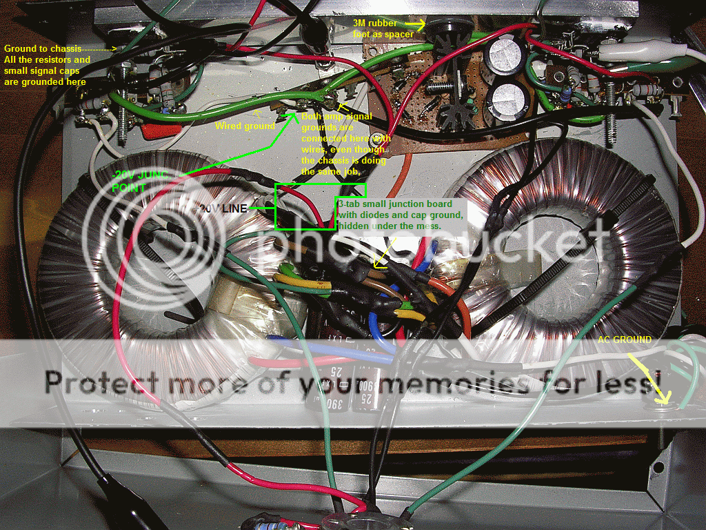
About the humming, maybe pictures will help find out what the problem is 😀 (There is no shielding, but I don't know where to put it exactly).
pass: yamahaphono
album: JLTIDIY
http://s109.photobucket.com/albums/n44/antdes45/JLTIDIY/
pass: yamahaphono
album: JLTIDIY
http://s109.photobucket.com/albums/n44/antdes45/JLTIDIY/
Any transformers or mains leads crossing signal wires or in close proximity? Once we take care of the basics it should not hum... ran same buffer before... I assume you spent some time copying te grounding instructions from the site...
Well, everything is close to the transformers.Any transformers or mains leads crossing signal wires or in close proximity?
Actually, no matter how I move the signal wires, the hum stays the same. If I disconnect the tube output signal wire from the tube and ground it, there's no more hum. Instead, there's a much quieter buzz sounding like a ground loop(And, well, if it's left floating, I'm about to destroy my speakers just like during the amp's startup if it's not muted).
Should I remove my wired star ground if the chassis is already connecting my 4 main grounding points together?
Two last things, the hum stays the same no matter how I place the tube.
Also, when there is nothing connected at the input and I rise the volume, the speakers wobble at 3-5Hz. Oscillation?
Same hum from the other channel, which I just tried. It acts the same when starting the unit up.
They suggest to leave the filament on all the time. I understand why now. 😉
Right now it sounds like a guitar amp. I'm not sure of what to do, moving the wires changes nothing, grounding at different places either, only playing with the connections between the tube and the filament PSU or the tube's output does.
Could it give any hints if the hum level "bounces" when something else is turned on on the same 120v circuit?
http://www.diyaudio.com/forums/showthread.php?s=&threadid=48109&highlight=
I found this topic for a soft start circuit. However, I'm not sure of how to get a 20 sec delay for both chips at the time.
All I know is that 8.7kOhm max to Vee is needed for an always-on one resistor unmute circuit.
I tried http://www.diyaudio.com/forums/attachment.php?s=&postid=538979
With R2=5k, R1=10k & C1=570µF, I get a 1.5 sec delay, so, will I need a giant 10000µF cap to have a proper delay or is there a better/smaller solution? So far, it's going to be an 8kOhm resistor and a switch.
I still think there may be some magnetic field interaction from the transformer.. but am allowing my mind to dwell on this one...
Please test that ground on in and output jacks are isolated from the case... multimeter with continuity tester will do...
is that gridstopper nice and close to the tube pin (the 3k9 on input side)...
Try bypassing cathode resistor with 100 - 1000uf electrolytic... negative side to ground...
give me some info on your earth wires... starting at the socket on the case....
Not at all, I have non-insulated chassis mount RCA jacks.Please test that ground on in
I'd say an inch or two from the tube, they are directly on the potentiometer pins. The tube's output has 10" of wire though.is that gridstopper nice and close to the tube pin (the 3k9 on input side)...
I need help here! The 10k to -20v?Try bypassing cathode resistor with 100 - 1000uf electrolytic... negative side to ground...
(I tried an 8µF NP 'lytic there, and it just freaks out more.)
And, here's the ground:

Well, I cut the signal ground cables going to the middle for no reason, and no change.
Connecting/disconnecting the 3-prong ground doesn't change anything as well.
The only other things could be resistor position, unreferenced(to ground) filament PSU, wrong resistor values because I use a ±20v PSU, using one rectifier for tube and amps, or transformer inductance.
And... I wonder now... Could the voltage just be too low for the tube? When the tube's output is grounded, all the "usual" hum disappears, and I hear some very faint transformer 120Hz hum when starting the amp instead of a loud 60Hz one.
Could there be an explanation as for why the amp goes crazy when there's no tube connected or it's not warmed up? (Tons of hum, and speakers are being pushed and pulled very hard to one side and the other)
EDIT: If I remove the tube, disconnect the 10k resistor between -20v and the tube's output, and connect the pot's output to the 3.3µF(bypassing the buffer), I get no hum at all. (A very quiet buzz is there instead, I'd need insulated RCAs)
Could the Bugle Boy 6DJ8 not be liking a ±20v supply? Or maybe the 10k resistor should have an other value with that voltage?
Sorry if I have misunderstood, but are the grounds all connected to the metal case, ie the case is acting as a ground star? 
- Status
- Not open for further replies.
- Home
- Amplifiers
- Chip Amps
- JLTI tube gainclone LM3886, no sound output