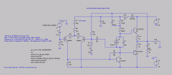
In the spirit of DIY, I've decided to offer a simple headphone amp. Gareth Ingram (aka Bigun) of Ontario will be directing this thread, schematic attached.
And here are the links to subsequent schematics:
Here are links to all the Haksa circuits courtesy of Gaetan, thanks mon ami!!
The amp; The Amp
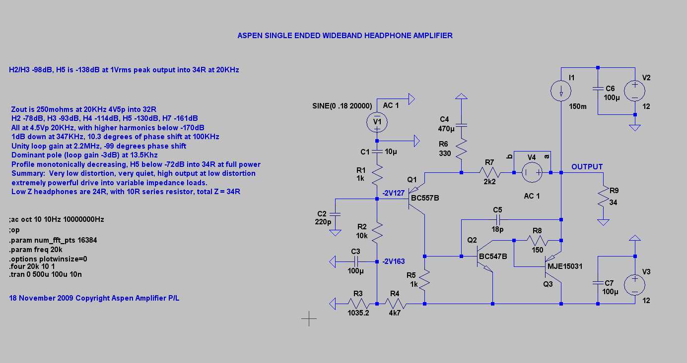
The same amp with a CCS; CCS
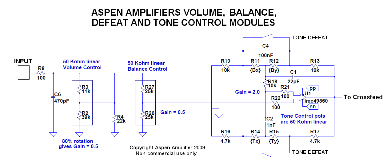
The tone controls with minor corrections, without the volume and balance controls; Tone Controls
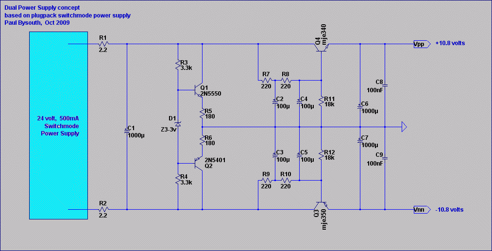
The power supply (not final schematic, may change); Power Supply
Cheers,
Hugh
And here are the links to subsequent schematics:
Here are links to all the Haksa circuits courtesy of Gaetan, thanks mon ami!!
The amp; The Amp
The same amp with a CCS; CCS
The tone controls with minor corrections, without the volume and balance controls; Tone Controls
The power supply (not final schematic, may change); Power Supply
Cheers,
Hugh
Attachments
Last edited:
Hi Hugh,
I would current source the diff. pair and VAS..................😀
I hope this is in keeping with the spirit of DIY.
Regards,
Jam
I would current source the diff. pair and VAS..................😀
I hope this is in keeping with the spirit of DIY.
Regards,
Jam
Last edited:
I would current source the diff. pair and VAS..................
Yes, Jam, I'm sure you would - and thousands of other designers.
However, that is a deliberate choice, and yes, I assure you, it's in the spirit of DIY!!
Cheers,
Hugh
Nice one Hugh!
Simple, easy to build and I'd guess as good (or better) than most out there. 🙂
Will Gareth work up a board for this?
Simple, easy to build and I'd guess as good (or better) than most out there. 🙂
Will Gareth work up a board for this?
Thank you John! High praise, from such an accomplished fellow......
The simplicity is important for builders, but belies some interesting things going on, as you are well aware. There are many AKSA concepts in this little amp.
I think Gareth might well do a board for this, though he wants to keep the 5200/1943 output devices for flexibility. However, I have reservations about this, as it will drive small speakers as it stands, and large outputs introduce more phase shift and make stability and SQ a bit more difficult.....
Cheers,
Hugh
Hello Hugh
Very nice and simple, for sure it will sound very good and there is a well chosen caps value for the vas and a phase lead cap.
Jam
You can just use a zener, a resistor and a cap for the diff. pair and VAS regulation, I do that in my own amp and it's very good and simple.
You can also match VBE and HFE of the two diff. pair transistors.
And, After adjusting P1 offset, if you adjust R4, so R2 and R3 will have same DC voltage drop, you will gain more definition and better soundstage.
I alway do those two things in my amps.
Thank for this headphone amp Hugh
Bye
Gaetan
Last edited:
First, thanks for sharing your design.
Second, couple of quick questions. What's your recommendation for v4? Has anyone built this yet?
Second, couple of quick questions. What's your recommendation for v4? Has anyone built this yet?
Last edited:
Member
Joined 2009
Paid Member
It doesn't take long for an idea to gather some speed around here 😀
I've always thought this general topology (RCA, TGM, D.Self etc.) to be a winner. It's flexible, robust, great sounding and a good path forward for DIY if you've started with a chip-amp or similar.
One thing about a power amp for DIY are a few subtle and not so subtle things you have to worry about, such as power supply, safety, thermal management, device reliability etc.
So a better starting point is lower power. I thought it would be great to have an amplifier for my desktop that could drive some desktop monitors and yet doubled up as a high quality headphone amplifier.
As Hugh says, I'm tempted to keep the power output devices in place for driving the desktop monitors. These are typically small inefficient drivers, not always 8 Ohm so a bit of grunt will be helpful.
But let's see how it develops...
My starting point is a maximum output of +/-8V into 8 Ohms working in ClassAB, allowing for transient swings up to +/-12V would imply a +/-15V supply. I would set up the biass current through the output devices so that they stay in Class A when driving a set of 23 Ohm headphones. Best of both worlds.
Member
Joined 2009
Paid Member
Hi Hugh,
I would current source the diff. pair and VAS..................😀
I hope this is in keeping with the spirit of DIY.
Regards,
Jam
Hi Jam,
That would certainly clean up the performance of the LTP and put a firmer grip over the VAS.
On the other hand, the bootstrap is so efficient, small parts count, low cost, reliable and gives excellent results. I've used this approach before and love the results, I believe it's more 'musical'.
A current source on the LTP is a good option for improved PSRR and other things. It could be more important with the relatively low supply rails because we can't use such a high value resistor if it's a simple feed. Again though, many good reports from amps which use a simple resistive feed in terms of musicality. Maybe we need to try it both ways ?
Hi Ikoflexer (should that be Harley, or Buell?),
Good question. You could actually simply use three 1N4148 diodes in a string. That should give around 2.1V of bias voltage, which would translate to 45mA of bias current. It's simple, and effective. Two of the diodes should be thermally coupled to the small heatsink used to keep the outputs cool.
This small amp has lots of phase margin, 75 degrees at 12MHz, the dominant pole. It would be very good with electrostatic headphones (Stax). There is a possibility that lag compensation (Cdom) could be reduced to 18pF. This would chiefly affect imaging performance.
Cheers,
Hugh
Member
Joined 2009
Paid Member
Nice one Hugh!
Simple, easy to build and I'd guess as good (or better) than most out there. 🙂
Will Gareth work up a board for this?
As you know I've enjoyed designed a few boards in the past, but I think Hugh needs something professional here so I'm going to lean on Aspen for some help with boards, take advantage of their supply chain 😀
This small amp has lots of phase margin, 75 degrees at 12MHz, the dominant pole.
12MHz??
The unity loop gain frequency is actually closer to 1.1MHz and the dominant pole frequency is a bit under 50kHz.
Member
Joined 2009
Paid Member
Let's see if a simulation file is helpful here (attached - my recreation of the schematic - Hugh, perhaps you can post your original file including the device models). I've opted for the infamous Vbe multiplier for now - can swap out for diode's later.
To use the sim, download it and change the file extension from .txt to .asc (LTspice). You may need to go into file options to view the file extensions.
To use the sim, download it and change the file extension from .txt to .asc (LTspice). You may need to go into file options to view the file extensions.
Attachments

Member
Joined 2009
Paid Member
Power supply
I see this as a desktop unit so my first thought was not batteries despite the noise benefits because I don't want to be worrying about re-charging etc.
If we want to keep this simple I'm leaning towards a 20VA trafo, anything too small will have poor regulation ? IF it is to drive small monitor speakers as well, I'd want 50VA.
Current draw on the rails is small, perhaps we can get away without dual supplies, put some fairly stiff CRC or CLC filtering in place on the rails if current draw is limited to headphone use only.
Another option would be a capacitance multiplier. It's a bit crude, but does the job well. The downside is some loss in headroom since you have not just the Vbe drop but Vce under load and the drop across the base resistor.
I'd like to keep it really simple - my dream would be a single pcb for both channels and power supply - how fussy should we be, can we achieve -100dB cross-talk on a single pcb ?
What are you thoughts ?
Hi Ikoflexer (should that be Harley, or Buell?),
It's just a plebeian wee-strom, but I love it.

I'd like to keep it really simple - my dream would be a single pcb for both channels and power supply - how fussy should we be, can we achieve -100dB cross-talk on a single pcb ?
What are you thoughts ?
I think so but where the amp itself is simple, I'd like to see extra effort on the PS. For a low current draw amp like this going with a fully regulated supply makes sense.

- Home
- More Vendors...
- AKSA
- Aspen Headphone Amp