Having developed a number of horns using CNC routing, I thought I'd play around with the Bruce design to get it curvy. Dave D has shared some material on this as well.
http://gallery.audioasylum.com/cgi/...serImages=7324&session=&invite=&w=1494&h=1339
http://gallery.audioasylum.com/cgi/...serImages=7324&session=&invite=&w=1447&h=1314
http://gallery.audioasylum.com/cgi/...serImages=7324&session=&invite=&w=1394&h=1326
The ribbing inside the comp chamber is purposely irregular.
Andrew
Any chance you could post them here? Unfortunately, to access your links, one has to be a contributer to AA. Which I'm not. I rarely visit, & have never posted there. I've seen too many conversations descend into insult-hurling competitions, and as far as I'm concerned, I can do without that. Life is too short.
Does this help?
http://gallery.audioasylum.com/cgi/..._28ATI090303A29_3D_Styles_1.jpg&w=1494&h=1339
http://gallery.audioasylum.com/cgi/...28ATI090303A29_3D_Styles_B1.jpg&w=1447&h=1314
If not, I'll have to get new photos because of the image size restrictions.
http://gallery.audioasylum.com/cgi/..._28ATI090303A29_3D_Styles_1.jpg&w=1494&h=1339
http://gallery.audioasylum.com/cgi/...28ATI090303A29_3D_Styles_B1.jpg&w=1447&h=1314
If not, I'll have to get new photos because of the image size restrictions.
(quotation from removed post also removed.)
These look good! I also prefer the second design shown out of the two gallery links you posted. Not totally keen on the legs at the back myself, I'd prefer a more or less solid block here, with mabye another hole through it?
A GIF filetype could be used for these and is more suitable than JPEG whilst being a little more efficient")
These look good! I also prefer the second design shown out of the two gallery links you posted. Not totally keen on the legs at the back myself, I'd prefer a more or less solid block here, with mabye another hole through it?
A GIF filetype could be used for these and is more suitable than JPEG whilst being a little more efficient
Look very nice I have to say (the speakers darling, the speakers ) -I like the 2nd one myself, with the straight legs (Nurse!) & circular brace.
The legs could be a possible issue; they'll need some cross-bracing at least just to make sure they're not vibrating too much. Still, nice work. I like them. Great artistry.
The legs could be a possible issue; they'll need some cross-bracing at least just to make sure they're not vibrating too much. Still, nice work. I like them. Great artistry.
I thought these sorts of posts were only seen on Audio Asylum?
One guy on that forum disclosed to me that they purposely use foul language as a tactic for the moderators to shut down a thread they don't like. Nice.
Anyway...
Thanks for the ideas on the comp chamber work. I'll try and get a new pic today.
One guy on that forum disclosed to me that they purposely use foul language as a tactic for the moderators to shut down a thread they don't like. Nice.
Anyway...
Thanks for the ideas on the comp chamber work. I'll try and get a new pic today.
(quotes from removed posts also removed)
Just as a general piece of information, a BLH doesn't really have a compression chamber per se, other than the room it is in. A low-pass filter chamber, yes, & the vast majority, including Bruce, can be regarded as variations on the bass reflex theme.
FWIW, the most effective place for the ribbing you mention would be on the side-walls, which are the largest parallel panels. It will still need some damping of course, but possibly a little less than the stock design.
More the better.
Thanks for the ideas on the comp chamber work
Just as a general piece of information, a BLH doesn't really have a compression chamber per se, other than the room it is in. A low-pass filter chamber, yes, & the vast majority, including Bruce, can be regarded as variations on the bass reflex theme.
FWIW, the most effective place for the ribbing you mention would be on the side-walls, which are the largest parallel panels. It will still need some damping of course, but possibly a little less than the stock design.
I'll try and get a new pic today.
More the better.
Scottmoose said:
FWIW, the most effective place for the ribbing you mention would be on the side-walls, which are the largest parallel panels. It will still need some damping of course, but possibly a little less than the stock design.
More the better.
Mmmmm. I was hoping to avoid that...given all the routing work is NOT on the sides. But, I'll work on something especially....probably using som sort of accousic foam in addition to the routered waves.
Thanks for the heads up on the wording of CC...I guess I'm using that wording because most people know what it is...still, sloppy.
For the benefit of those having troubles viewing Andrew's images i have attached them in a more functional format.
Here are some constructive critism i sent to Andrew on these by email last night (edited to reflect what others have posted)
--------
Those are all kind of pretty -- but over the top to my eye. Issues i see:
1/ Even if you are using plywood, you have to keep in mind that the way you are cutting the wood is not playing to its strengths. For mdf i'd suggest a minimum of 40mm wall thickness, plywood could be a bit thinner,
2/ mdf will need to be finished inside and out with something that drys very stiff that soaks into at least the top couple mm. Still i doubt that will get rid of the mdfs negative energy storage (generally by the time this step is added it is cheaper & easier to start with ply or solid anyway). Another way to minimize mdf's issues (and solid wood for that matter) is to use more thin layers (ie something like 3-6 mm slices)
4/ Even with plywood, 20 mm is a minimum for side panels... we found in Maiko that this wasn't enuff and that is a 5" driver.
5/ (this echos Scott's comments) i like the direction you are taking with the inside of the BR chamber, but the variations are not large enuff to make a serious difference. Better to use all the available space and have large variations (on the order of 20-30% of the distance to the opposite wall) -- don't forget the sides either. Some bracing and variation there would be good too (and as the only expanse of parallel surfaces, by far the most important).
--------
It would be pretty easy to make the inside of the BR chamber quite complex. I'd use all the volume available to create a lattice of bracing and deflector/ripply surfaces. It would mean making all the layers in one half of the box different from each other (and then reflect a duplicate across the centre line -- top to bottom symmetry means you only need to work out 1/4 of the speaker volume. I'd also work in the very useful driver brace)
If Andrew is going to have a go at these, it behooves us to help him make the best one possible.
dave
Attachments
Yes indeed.
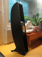
For reference, 'ere is how the original curved Bruce cabinet (which I thought at the time, and still think, looks stunning) was done. I don't believe it was CNC machined, or had the routing on the internals of the back-chamber surfaces, so the current proposals could take things to the next level.
Having had a few hours to reflect on the projected plans, of the 4 diagrams shown so far, my favourite is the one to the bottom-left of Dave's attachment, without the overly fussy additional back panel & bracing. Where I would modify it further is to curve this rear panel too slightly a la the original Curved Bruce, This should bring additional stiffness benefits.
Attachments
Here's the latest drawing...taking into account feedback from others.
http://gallery.audioasylum.com/cgi/wi.mpl?u=7324&f=Bruce-Collect28ATI090303A291bit.gif&w=2026&h=1930
http://gallery.audioasylum.com/cgi/wi.mpl?u=7324&f=Bruce-Collect28ATI090303A291bit.gif&w=2026&h=1930
Hey guys. It's great to see this collaboration and development. Curvy Bruce 2 looks really nice... I would not ming giving one of those a shot at some point in the near-ish future.
I look forward to seeing the output from this made available to the DIY community; CNC-friendly drawings would be very helpful for some DIYers.
Good work guys.
I look forward to seeing the output from this made available to the DIY community; CNC-friendly drawings would be very helpful for some DIYers.
Good work guys.
Wow - These designs look amazing - well done.
I recently had some CNCing done for a project. I used 24mm BB ply, and used a similar laminating process. The finish that you can achieve having sanded, stained, sealed, sanded, sealed again , sanded, and finally wax polished, is beautiful and very satisfying.
One caveat: Even with the finest CNC tolerances the edges need some work to get smooth. This is obviously important where you can see, for aesthetic purposes.
Is it important to have a smooth interior? Access to sand the tight parts will be difficult. My narrowest part was 120mm wide, and I was glad that it was not any less.
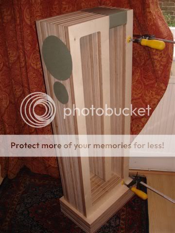
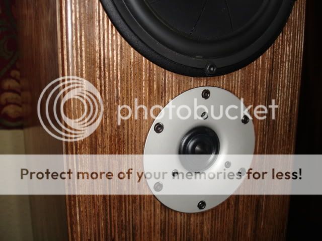
The flash photography makes this look rougher than it is. It is silky smooth, and shiny.
I recently had some CNCing done for a project. I used 24mm BB ply, and used a similar laminating process. The finish that you can achieve having sanded, stained, sealed, sanded, sealed again , sanded, and finally wax polished, is beautiful and very satisfying.
One caveat: Even with the finest CNC tolerances the edges need some work to get smooth. This is obviously important where you can see, for aesthetic purposes.
Is it important to have a smooth interior? Access to sand the tight parts will be difficult. My narrowest part was 120mm wide, and I was glad that it was not any less.
The flash photography makes this look rougher than it is. It is silky smooth, and shiny.
dublin78 said:Wow - These designs look amazing - well done.
They still have a ways to go... the interior is better, but there are voids that could be better utilized, the 2 major parallel sides are still there -- the greater range on the internal bits do act as the braces that are implicit in the design.
dave
The finish that you can achieve having sanded, stained, sealed, sanded, sealed again , sanded, and finally wax polished, is beautiful and very satisfying.
Beautiful indeed. I love being able to see the plys (sp?) like that. Lovely.
Cheers
dublin78 said:Couldn't you simply add some blocks or domes to the inside side panels to break up the parallel problem?
You could. But with the CNC why not build it into the design?
dave
Some lay-person suggestions:
1. BR chamber - extend into the voids, then use deeper peaks and valleys to break-up lower freq. (I think). Could Schroeder (sp?) calcs be used? Hmmm, perhaps the space in the BR chamber would be too limited and pressurised for those types of calcs to have any effect?
2. Aesthetics - I prefer the leg style of the top right in P10's drawings; the Curvy Bruce 2 legs make it look somehow dumpy, tho may look okay if painted in strong primary colours for a 'modern' look.
3. If it is going to result in a practical material saving, I prefer Curvy Bruce 2, because it lacks the rear voids. It also keeps the weight down to a minimum.
I know you guys have probably thought of this, but it would be nice to see the CNC plans/templates/whatever they are called designed to minimise waste. We have enough waste in this world as it is... Looking side-on, would breaking the design into 3 or 4 pieces help reduce waste? This would also allow a smaller packing size. Just thinking out loud...
Cheers
- Status
- This old topic is closed. If you want to reopen this topic, contact a moderator using the "Report Post" button.
- Home
- Loudspeakers
- Full Range
- New designs for Curvy Bruce