Dear fellow DIYers,
I recently joined the word of tube and wanted to start my first headphone amp. project with the optimized morgan jones design.
ref:
http://www.headwize.com/projects/showfile.php?file=cmoy5_prj.htm
One problem that I came with is there is an option for a output transfomer. During my research, I found out transformer at the output stage is considered more suitable for tube amps.
I know usually the secondary impedance is 4 or 8 ohms (fine, typical speaker impedance), but I have no idea what is the usual input impedance value? I saw some are 3.5K where some are just down to even 600 ohm.
My question here is, what actually determines the primary impedance of the output transformer? Is it the ratio of primary and secondary volage or something else?
If I custom made some output transformers, could the secondary impedance have some value other than 8 ohms?
Thanks very much for your input,
James
Hi
Transformers 'reflect' an impedance from one side to another, in a ratio determined by the turns on the primary and secondary.
The voltage ratio from one side of the transformer to the other is Np/Ns
And the impedance ratio is the above ratio squared
so for example if you have an output transformer with a 10:1 voltage ratio, it has an impedance ratio of 100:1
therefore if you connect an 8 ohm impedance to the secondary, a speaker say, it reflects back 800 ohms on the primary.
Similarly, an impedance ratio of 1000:1 would reflect a 8000 ohm load on the output tubes if an 8 ohm speaker were terminated on the secondary.
Manufacturers provide addition taps/windings etc, to maintain 8000 ohms on the primary, when 4 ohm speakers need to be used.
does that help?
A transformer doesn't really have a primary or secondary impedance. The impedance of the primary is determined by the impedance of the load on the secondary multiplied by the square of the turns ratio. So if, for example, you have an 8 ohm speaker across the secondary and the primary turns = 20 x the turns on the secondary, then the primary impedance = 8 x 20 x 20 ohms = 3,200 ohms. If you put a 200 ohm headphone on the secondary, the primary impedance will be = 200 x 20 x 20 ohms = 80,000 ohms.
In general, output transformers are made for speakers and are unsuitable for headphones. The few that are on the market for phones are expensive.
One way out is to use a speaker transformer with a dummy load (e.g. an 8 ohm 15 watt resistor), and then connect the headphones in parallel with the dummy load, maybe with a series resistor to limit the signal voltage delivered to the phones for protection. I've seen an example on this site.
Another way is to use a toroidal mains tranformer of the required turns ratio (voltage ratio). Toroids have good bandwidth and some people say they work well for phones.
Yet another way is to make your own transformer, as you propose.
Whoa, watch out... While it is true that transformers reflect impedances, the impedance they can reflect is finite, and is as a simplification limited by the primary winding reactance on the low end, and leakage inductance on the high end.
When the reflected load impedance becomes a significant % of the winding reactance at a given frequency the distortion will start to increase as the now none ideal transformer's primary reactance appears in parallel with the reflected load. This limits the highest impedance that can be matched, and is also a fact of life that limits LF extension in all audio transformer applications. You can see this effect as the -3dB response moves higher with increases in load impedance. (No global negative feedback applied! Triode amplifiers also exhibit slightly different behavior in this regard. The assumption I make here is that the transformer is driven by a non ideal voltage source with a relatively predictable source impedance or is driven by a current source such as a pentode.)
Leakage inductance is a parasitic inductance that appears in series with the primary and has the effect of limiting HF response, in this case as the reflected load impedance decreases the effect of the leakage reactance becomes more pronounced - also the case as the frequency goes up as the effective leakage reactance also increases. (Worst case here is low source impedance and load impedance.)
These are just two non-ideal behaviors that limit a transformer's ability to transform impedances. DCR obviously also plays a role as does the core's magnetic properties.
I haven't probably explained this all that well, but hopefully I have added something for further discussion.
In terms of MJ's headphone amplifier a limited ratio of 2:1 is probably more than enough to accommodate real world headphones
as this would reflect 32 ohms to the amp for an 8 ohm headphone and about 250 ohms for a 64 ohm set of phones. Voltage compliance is probably the practical limit for choosing a transformer here. For 32 ohm phones and up a transformer is probably not required.
The transformer in this design is only needed for low impedance headphones.
Do you already have headphones that you want to use? If so, do you know their impedance? It would be good to actually have a plot of impedance vs frequency.
The selection of an appropriate output transformer depends on this impedance curve.
P.S. please also note the voltage rating on that output cap. This is very important for your safety! Adding an output transformer will also improve the safety by providing additional isolation from HT.
billr
Yeah, your answer definitely helps. So I understand the transformer does not really have anything to do with impedance expect it firstly bring down the source output voltage to an appropriate level suitable to drive the speaker, and the impedance is really the side effect.
As a result, a 3.5K : 8ohm output transformer is just saying a 20:1 turn ratio in another way??
ray_moth
yeah, I have seen many topologies using dummy load method, but isn't it more appropriate to use 8 = Rdummy*Rheadphone/(Rdum+Rhp)
to calculate the dummy load because we can give a better impedance matching?
kevinkr
Iain
I mainly use low cans such as AKG 701 and AudioTechnica W5000. Both have pretty low impedance. Actually I don't really know how to compose a specification for a transformer based on load impedance, do you have more materials I can refer to?
Again, thanks for all the inputs. So glad that I can learn so much here!
James
Yeah, your answer definitely helps. So I understand the transformer does not really have anything to do with impedance expect it firstly bring down the source output voltage to an appropriate level suitable to drive the speaker, and the impedance is really the side effect.
As a result, a 3.5K : 8ohm output transformer is just saying a 20:1 turn ratio in another way??
ray_moth
yeah, I have seen many topologies using dummy load method, but isn't it more appropriate to use 8 = Rdummy*Rheadphone/(Rdum+Rhp)
to calculate the dummy load because we can give a better impedance matching?
kevinkr
This is more clear now. So I can say that, driving a headphone with transformer output, the main consideration is to adjust the output voltage to an appropriate level rather than doing any impedance matching?as this would reflect 32 ohms to the amp for an 8 ohm headphone and about 250 ohms for a 64 ohm set of phones. Voltage compliance is probably the practical limit for choosing a transformer here. For 32 ohm phones and up a transformer is probably not required.
Iain
Do you already have headphones that you want to use? If so, do you know their impedance? It would be good to actually have a plot of impedance vs frequency.
I mainly use low cans such as AKG 701 and AudioTechnica W5000. Both have pretty low impedance. Actually I don't really know how to compose a specification for a transformer based on load impedance, do you have more materials I can refer to?
Again, thanks for all the inputs. So glad that I can learn so much here!
James
pkjames said:Dear fellow DIYers,
I recently joined the word of tube and wanted to start my first headphone amp. project with the optimized morgan jones design.
ref:
http://www.headwize.com/projects/showfile.php?file=cmoy5_prj.htm
One problem that I came with is there is an option for a output transfomer. During my research, I found out transformer at the output stage is considered more suitable for tube amps.
I know usually the secondary impedance is 4 or 8 ohms (fine, typical speaker impedance), but I have no idea what is the usual input impedance value? I saw some are 3.5K where some are just down to even 600 ohm.
My question here is, what actually determines the primary impedance of the output transformer? Is it the ratio of primary and secondary volage or something else?
If I custom made some output transformers, could the secondary impedance have some value other than 8 ohms?
Thanks very much for your input,
James
I have just capacitively coupled valve pre amps into power amps with no problems. So long as the impedance isnt too low at the power amp end things should work fine.
pkjames
To determine just which OPT you want to obtain, you have to consider the actual working load that the transformer provides to the tube. Reflected load is one component. The RP or plate resistance is another part and the actual DCR of the OPT primary is the last part. If you add the reflected impedance (Rl) in parallel with the Plate resistance (Rp) and then add that sum to the primary DC resistance of the OPT as a series added resistance, you will have the complex impedance load that the OPT primary must provide to the tube plate.
To determine which transformer will meet this load, divide this impedance by 2 X pi and the lowest frequency of interest (i.e. 20Hz). This will provide the amount of inductance you need in the primary. But, this will only provide for a -3dB performance at this point. To obtain a -0.5 dB performance you must have 3.63 times this calculated inductance. But, you only need this amount as a maximum performance number, under load and making music.
Now, most inductance values quoted are at a minimum flux point of 1 vac and 120 Hz. A gapped core transformer rated to handle 20 to 40 ma DC will typically have twice this measured inductance, as a maximum amount. An un gapped transformer will typically have 10 times this amount as a working maximum. For SE you must have a gapped transformer.
So, when looking, make sure you know what the expected primary inductance is and how they arrived at that number. Is it measured at 1 vac & 120 hZ, as most mfg's supply, or is it the maximum loaded operating number, as Lundahl typically provide? Then you need to determine the plate DC current that will pass through the OPT primary and make sure the OPT is designed for pretty close to this amount, not more than 1.5 times that current number.
If this doesn't click in your head I can do the math for you too. But I think you should go to Franks Tube Data, down load the appropriate tube data sheets and struggle with this actually fairly simple problem, so you have it down cold, for future projects.
Bud
pkjames said:billr
Yeah, your answer definitely helps. So I understand the transformer does not really have anything to do with impedance expect it firstly bring down the source output voltage to an appropriate level suitable to drive the speaker and the impedance is really the side effect.
I think it's better to think of it that the headphones are too big a load for the tubes to drive direct so a transformer converts the low impedance headphone up to a nice high impedance for the tubes to drive. There's no magical formula other than laws of physics, but some transformer ratios will be better than others for your application. You either model all the variables or tune by ear (or both)
No doubt this is a particularly bad noob question, but hours of searching has netted no answers 
How do we determine what primary impedance our OPT should have? (I realise the impedance we end up with depends on the secondary load. I want to drive 64ohm headphones, but I need to know what to present to the valves before I can choose a suitable OPT.)
How do we determine what primary impedance our OPT should have? (I realise the impedance we end up with depends on the secondary load. I want to drive 64ohm headphones, but I need to know what to present to the valves before I can choose a suitable OPT.)
Whoa, watch out... While it is true that transformers reflect impedances, the impedance they can reflect is finite, and is as a simplification limited by the primary winding reactance on the low end, and leakage inductance on the high end.
When the reflected load impedance becomes a significant % of the winding reactance at a given frequency the distortion will start to increase as the now none ideal transformer's primary reactance appears in parallel with the reflected load. This limits the highest impedance that can be matched, and is also a fact of life that limits LF extension in all audio transformer applications. You can see this effect as the -3dB response moves higher with increases in load impedance. (No global negative feedback applied! Triode amplifiers also exhibit slightly different behavior in this regard. The assumption I make here is that the transformer is driven by a non ideal voltage source with a relatively predictable source impedance or is driven by a current source such as a pentode.)
Leakage inductance is a parasitic inductance that appears in series with the primary and has the effect of limiting HF response, in this case as the reflected load impedance decreases the effect of the leakage reactance becomes more pronounced - also the case as the frequency goes up as the effective leakage reactance also increases. (Worst case here is low source impedance and load impedance.)
These are just two non-ideal behaviors that limit a transformer's ability to transform impedances. DCR obviously also plays a role as does the core's magnetic properties.
...
pkjames
To determine just which OPT you want to obtain, you have to consider the actual working load that the transformer provides to the tube. Reflected load is one component. The RP or plate resistance is another part and the actual DCR of the OPT primary is the last part. If you add the reflected impedance (Rl) in parallel with the Plate resistance (Rp) and then add that sum to the primary DC resistance of the OPT as a series added resistance, you will have the complex impedance load that the OPT primary must provide to the tube plate.
To determine which transformer will meet this load, divide this impedance by 2 X pi and the lowest frequency of interest (i.e. 20Hz). This will provide the amount of inductance you need in the primary. But, this will only provide for a -3dB performance at this point. To obtain a -0.5 dB performance you must have 3.63 times this calculated inductance. But, you only need this amount as a maximum performance number, under load and making music.
...
Bud
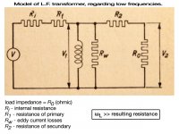
Experiencing the low roll off described by Kevin with a standard 5K:8 ohm, I wonder if output transformers exist with suitable inductance to overcome this problem. This model of the OT describes the effect: to fall of at 20Hz
2 pi 20 L >> resulting resistance network
Attachments
disco,
To keep from having to spend relatively large amounts of money, look through Edcore and Hammond catalogs. If you find an appropriate looking device, from the load line point of view, get in touch with the company and ask them for inductance, and whether this inductance is at 1 vac 120 Hz or what is expected at 4 kilogauss, the general maximum permeability point of core.
If you are dealing with a gaped transformer, for SE use, ask what the total gap size is and how much DC current from the plates they think the transformer will support.
Then, bring this info here, along with the tube in question, and we can do the math and you can see how to look for transformers for specific low frequency applications.
A long time ago, Dr Partridge, one of the leading audio transformer designers of all time, pointed to there being a limit to the amount of inductance you can throw at a problem load. His finding was that anything better - 1.0 db, at the frequency of interest, would only increase distortion. And, that this increase would be for both above and below that frequency. The RDH3 has a small monograph about this, but it is omitted in RDH 4.
So, it is not a simple problem and depending upon what type of drivers are involved, you may want that lowest distortion point at, say, 40 Hz rather than 20 Hz.
Bud
Hi Bud,
Thank you for helping out here, the money's already spend though Got me some C-core SE 4K:100/200/300 usable up to 50mA DC current. Fired up the old Wayne Kerr component bridge and the primary holds 20.5H, Rpri= 314 ohm, Rsec300= 44 ohm.
I've used these OT with good results on 400 ohm speakers with 1626 triodes (Ri=1K6). Looking at this headphones amp I got the idea to power my 300 ohm Sennheisers with them. Bass was lacking though. Ri of the 12B4 is about 1K ohm (25mA), Vplate 250V.
Will ask the producer about gab size and permeability but the answer won't come soon I guess.
Jaap
Thank you for helping out here, the money's already spend though
Got me some C-core SE 4K:100/200/300 usable up to 50mA DC current. Fired up the old Wayne Kerr component bridge and the primary holds 20.5H, Rpri= 314 ohm, Rsec300= 44 ohm.I've used these OT with good results on 400 ohm speakers with 1626 triodes (Ri=1K6). Looking at this headphones amp I got the idea to power my 300 ohm Sennheisers with them. Bass was lacking though. Ri of the 12B4 is about 1K ohm (25mA), Vplate 250V.
Will ask the producer about gab size and permeability but the answer won't come soon I guess.
Jaap
Attachments
disco,
Your inductance is fine, you only need 19.5 henry for the 890z ohms this tube requires. Your load line is pretty steep though, some four times what the plate requires for A1 operation in SE. That, coupled with the rather high secondary DCR is probably what is causing the loss of bass. Just not enough power to drive the load with the reflected loses in the transformer.
When you provide a tube with a load line that accentuates the voltage output and then provide also provide a lot of DCR loses in a transformer, for that voltage to overcome, you have this result. Your turns ratio provides a 257 z ohm secondary output, when loaded to a 12b4-A tube with the turns ratio you have specified.
It is a mistake to assume that the transformer should be physically small because the power going through it is small, when involved with tubes. They are a voltage device, using the transformer to convert the voltage biased character into a current biased character and so are very sensitive to transformer DCR. The transformer for your needs should have about 100 ohms max in the primary and no more than about 10 ohms in the secondary.
Bud
Last edited:
Hi Bud,disco,
Your inductance is fine, you only need 19.5 henry for the 890z ohms this tube requires. Your load line is pretty steep though, some four times what the plate requires for A1 operation in SE. That, coupled with the rather high secondary DCR is probably what is causing the loss of bass. Just not enough power to drive the load with the reflected loses in the transformer.
When you provide a tube with a load line that accentuates the voltage output and then provide also provide a lot of DCR loses in a transformer, for that voltage to overcome, you have this result. Your turns ratio provides a 257 z ohm secondary output, when loaded to a 12b4-A tube with the turns ratio you have specified.
It is a mistake to assume that the transformer should be physically small because the power going through it is small, when involved with tubes. They are a voltage device, using the transformer to convert the voltage biased character into a current biased character and so are very sensitive to transformer DCR. The transformer for your needs should have about 100 ohms max in the primary and no more than about 10 ohms in the secondary.
Bud
Would some more power bring better low end control with this peculiar OT? I'm thinking about the 45 triode for which a 4K load would be practical. Won't the high output impedance cripple bass control, driving 300 ohm headphones?
Jaap
- Status
- This old topic is closed. If you want to reopen this topic, contact a moderator using the "Report Post" button.
- Home
- Amplifiers
- Tubes / Valves
- Output transformer impedance question