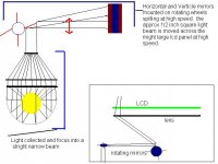
from the post on using laser beams for a projector I had this idea. Instead of using a light source on an entire lcd panel to provide light to project the image, why not use a norrow beam of light and move it rapidly across the panel. Instead of using a 575w light to light a 10 inch panel, why not focus the light down to say 1/4 of an inch and scan it across the panel like a crt. it would be a large device but if it works would yeld a very bright image. I enclosed a very rough sketch of the idea.
Attachments
That will work
You cannot focus your beam into a collimated beam any smaller than the original light source but since the arc lenght in a Metal Halid is 7mm that is small enough.
You will need a high speed on your rotating polygon to sweep a screen at sufficient rate to avoid flicker.
Can be done if you are keen.
Have a look at my thread Laser projection for some details on cheap polygons etc.
I am a big junkaholic (i.e. old electronics). But anyway, for high speed on the rotating polygons, you could go with just about any small motor. The ones in toy cars, and the ones in tape players happen to rotate quite fast. Another alternative would be loud, but a black and decker wizard motor would be the fastest. 5000rpms or somthing to that nature are what it goes at. Great idea!
This would work if the LCD was truly a "raster-scanned" device as well, like a CRT, however, it is not. Every pixel is "active" at all times, but the value of the pixel will change at the scanning rate. To that end, I am not sure what the benefit of the described system will be.
Alvaius
Alvaius
alvaius
To that end, I am not sure what the benefit of the described system will be.
I will educate you. Pay attention.
mikejz84 says why not run a beam of light across the panel.
Ok now as everyone knows the pixels in an LCD are active whether there is any backlight or inline lighting or not.
So if you shone a tourch through the panel you would see a small area of picture. Not very helpful.
But if you rastered a light beam across the panel persistence of vision would let each illuminated area stay in your brain and you would still "see" a part of a picture even when the moving light beam has moved on. This is an essential part of CRT TV viewing.
Now sweeping out a picture has been tried many times before using moving light beams dating from the early 1930's with some success. However the thing that is hard to do is move a beam of light with the precision to draw a picture on screen with sufficient accuracy or speed. Big dollars involved.
But mikejz84's idea has a chance of sucess because he is only trying to illuminate a part of the LCD that already has had very precise electronics set the pixels.
He can come in with a much less precise device and illuminate not one line but several lines per sweep maybe 20 lines would be practical.
Now the essential thing is normally the light from a source is spread out over area X, but in mikejz84's idea he can concentrate all his light on a much smaller area thus acheiving far greater brightness per unit area and consequently you see a much brighter picture.
Of course he has to be above the flicker rate and it would take a lot of good engineering but it is possible.
I am aware of the perceived brightness increase from using a pulsed light source of higher peak brightness but the same average power. That will be a function of repetition rate (or frame rate in this case), and duty cycle, or spot size in this case. Would need some playing with spot size to achieve the best results.
My concerns are more about optics and mechanics. All pixels in the TFT are always active. For that reason, the spot that is generated must be a perfect multiple of the size of a pixel which will be pretty difficult to do. The other thing is that the scanning mechanism must be sub-pixel accurate. If either of these are not true, then you will have overlaps between your scans and will end up with hot (brighter lines).
The other issue is that the spot will need to be very even in terms of illumination. If it is not, as opposed to having slowly varying brightness, you will have rapidly varying brightness on the display which will be very perceptable to the human eye.
You will also have the issue of illumination angle of the pixels changing significantly from the inside to the outside of the display which will create brightness variations as well as brightness variations due to surface reflectance. You can fix this by moving the scanner farther from the display. This is different from an OHP where you essentially have a diffuser behind the display to ensure an even lighting condition for all pixels.
Interesting idea, but you still have the same practical limitations of any other scanned system.
Alvaius
I disagree
The idea has a lot of potential, has fewer problems than line by line scanning, would be relatively easy to implement and gives either a much brighter picture, or allows the use of lower wattage light source.
I agree with your thoughts on accurate scanning to overlap the light paths and I am not saying it is easy but the essence is using persistence of vision to advantage.
Ordinary leds can be pulsed as long as they stay within the average power ratings and this is done in for example systems for creating a beam across a doorway. Output from DC powered LED is much too low for anything past a few meteres yet pulsed one IR led transmitter can easily reach 20 meters. These are sold commercially. I have my own system at home. Details available if required.
Taking then the full output from a 400 watt Metal Halide to illuminate an LCD ow this works. Now consider if the beam were reduced to half diameter and shaped and scanned only the top half of the picture and then the bottom half.
It would not be all that difficult to acheive a seemlesss match at the half point and the light beam power per unit area is now doubled. So we now have an apparent 800 watt light bulb. Taking this to an extreme one could reduce the light to just one line and on a VGA screen you could be looking at approximately 400 times increase in light per area.
Or another way or saying it is a 400 x 400 = 160,000 watt light source
This increase is far beyond what could be obtained with an LED pulsed system.
Possibly 10 - 20 scans could be done with modest outlay. The advantage being a much brighter picture, a much larger picture capability, or, for a given screen size and brightness level, a much smaller bulb wattage. Perhaps even down to a 40 watt MH. Much less heat. Much less electricilty used.
Yes I have made a projector using a low power red Laser diode using a polygon scanner and a method of increasing the scan speed by placement of mirrors. You can see this fully described in Laser projector thread. You can see I am not unfamiliar with scanning.
For rotating the polygons I'm thinking of maybe the motor from a hard drive...hmm a fast precise drive that has a built in controll system...computer places everywhere have "dead" drives to give away. Most have bad sectors and thats the end....out and out failure is rare...except for Fuji drives.
just a stray thought..
zardoz
just a stray thought..
zardoz
Zardoz
You can buy suplus printer 3 phase polygon motors with controllers quite cheap. I got a set from Oatley Electronics in Australia for about $20 USD couple of years ago. They might have some more. Hard drives are stepping motors I think. Possibly want continuos rotation motors but a high speed stepper would do. Thats a good idea.
Normally when scanning you need a horizontal scanner to move the beam from left to right, and a vertical scanner to move the beam from the top to the bottom. In this case which is just an illuminator, It may be possible to just use a vertical scanner. If the light can be arranged as full width x say an inch then all thats needed is to move that down the LCD at a very modest speed. The human eye does not increase what it sees. You can look at an object all day and it does not get any brighter so I don't see any overlap problems. A width of constant illumination moving down the LCD screen should just uncover all of the LCD in a continuos sequential motion. I could be wrong on that but its an easy thing to prove without much cost and it eliminates one scanner and means the frame scanner only has to run at low speed.

While the eye does respond to peaks, this is not a linear response. Reducing the spot size by a factor of 400 and increasing the brightness of that spot by 400 times will not yield a 400 times increase in brightness. It is a complex relationship, and you can possibly achieve an increase in brightness of several times. I will dig through some of my SID literature to see if I can find any papers on it. I can vaguely remember a paper that discussed this on that other topic, scanning laser displays. If it was a purely linear relationship, you could use a low powered laser, but unfortunately, you still need a fairly high power level.
I would like to hear your thoughts on how you will achieve a spot size that is a perfect multiple of a pixel width, and also how you will move that spot a perfect multiple of a pixel. Even in a commercial application this would be very very difficult, for a DIYER, it may be impossible.
Have you considered this? As you scan that spot across the display, the distance from the light source\optics to the display will change. That means the size of the spot will change. You can reduce this to some degree with optics (now becoming quite long in order to achieve good collimation), but you are likely going to need to reduce the spot size as well such that changes in size are smaller w.r.t. a pixel.
Alvaius
alvaius
Quote by alvaius
While the eye does respond to peaks, this is not a linear response. Reducing the spot size by a factor of 400 and increasing the brightness of that spot by 400 times will not yield a 400 times increase in brightness. It is a complex relationship, and you can possibly achieve an increase in brightness of several times
*************************************
If you start of with a light flux of a certain value on a large area then concentrate the same illumination on a half sized area you will have doubled the flux. The fact the eye does not perceive it as double the flux because of its logorithmic nature is imaterial.
What I said was it would be equivalent to a 400 x 400 source and that is perfectly correct. I never said it would look 400 times as bright
My exact words
Or another way or saying it is a 400 x 400 = 160,000 watt light source
Try and read the information correctly.
On your other points please look at my post to Zardoz above which should answer your concerns.
I will guarantee that when I stop posting, and the others stop posting, you will also stop posting because it seems you have no positive information to post. Perhaps I am wrong. Let us hear your thoughts on this matter.
Actually I understood exactly what you mean't. It will not be effectively like a 160,000 watt source. I should look like a lot more than 400 though.
In terms of being positive, I think you are on the right track by only scanning in one dimension. It should make the overlap issues go away. It will be analogous to a focal plane shutter in reverse. The best results will likely be achieved if you follow the refresh by a little to give the pixel a bit of time to change. It will not settle in a frame time, but you can at least get a good portion of the transition in...
In terms of being positive, I think you are on the right track by only scanning in one dimension. It should make the overlap issues go away. It will be analogous to a focal plane shutter in reverse. The best results will likely be achieved if you follow the refresh by a little to give the pixel a bit of time to change. It will not settle in a frame time, but you can at least get a good portion of the transition in...
I just thought I could check back at the thread I have started here, I must admit I sure did learn a lot about my own idea! Anyways I do have some observations for you. The main area of objection concerning this idea is how to uniformly scan the light so that pixels are illumined evenly during a scan. However, while the idea is based on a crt, it is not a crt and crt scanning rules do not apply. I propose that instead of single pass scans, instead do multiple scans. The idea is to scan one axis at a higher rate then the other. For example, why not scan the vertical 20 times faster then the horizontal, and between every vertical scan move the horizontal 1/20th the width of the scan beam. That way instead of having to worry about a pixel being double scanned, and thus creating hot-spots, because each pixel will be scanned 20 times, the threat of slight misalignments is not much to worries about, the odds that a pixel being scanned 21,22,23, 24, or even 25 time being notice while others are scan 20 times is quite negligible as compared to a pixels scanned one or two times. Currently, I am not in a position to being work on this idea on my own, But I really thing that this is a idea that needs further development and I appreciate all of your input.
I think what remp proposed of only scanning in one dimension may be the easiest and most practical thing to do. You have to be careful that you are scanning somewhat in sync with the image being drawn on the screen. If you do not, you may have funny image artifacts. Depending on what is showing up on the screen, this may be minimal, i.e. if the image is static, but if there is a lot of motion in the image, it could be substantial.
Alvaius
Alvaius
alvaius said:I think what remp proposed of only scanning in one dimension may be the easiest and most practical thing to do. You have to be careful that you are scanning somewhat in sync with the image being drawn on the screen. If you do not, you may have funny image artifacts.
Alvaius
If one scanning frequency is faster than the other (horizontal versus vertical), you should try and scan a multiple faster than the slower, correct? I really like the idea of scanning each pixel multiple times in order to wash out artifacts.
Not sure of the feasability of this though, as many people struggle to just get one of the frequencies, much less a multiple thereof.
--Clint
Getting a multiple of the frequency or the exact frequency will be pretty easy. Just take the vertical sync signal and use that to drive what is essentially a PLL loop with a motor, some sort of feedback (encoder?), and the vertical sync signal. The encoder for feedback is an easy way go. You can get ones with "home" signals so you know exactly where you are w.r.t. the sync signals.
However, if you synchronize to the refresh, you may not need to go multiple and can just go with 1x the refresh rate.
Alvaius
However, if you synchronize to the refresh, you may not need to go multiple and can just go with 1x the refresh rate.
Alvaius
- Status
- This old topic is closed. If you want to reopen this topic, contact a moderator using the "Report Post" button.
- Home
- General Interest
- Everything Else
- The Moving Image
- DIY Projectors
- intresting new idea for lighting