Hi,
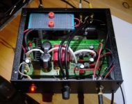
Finally got a chance to work on a new project... a buffered opa2134 headamp that i devined off of http://www.raymondaudio.nl/ as well as from the opa datasheet (a lousy design as it seems to invert; my beginner skill level interpretation).
Anyway. Built the thing (after completeing my modular transformer supply for it, or anything else I come up with), and it sounds fantastic! However there is one small multi-part question I have...
The noisefloor seems a bit too high... nothing problematic like harmonics, buzzing, nor radio stations coming through... just plain white noise.
a) When I turn off my power supply, about 2 seconds into the discharge (while audio is still playing, or not) the noise floor disappears. Odd, as I get a good 5~10 seconds of playtime. My PS/regulator seems to be working well, as well has having 10,000mf post-regulator + (2x)1000mf at each opamp.
b) By hand, I did try piggybacking 'R5' (100k feedback resistor; a bit too high for my taste) with a 20k in parallel, and levels seemed to drop a bit, but have no expertise if this was a good idea...? Would like to be sure before attempting to rework the guts...
c) the easiest way to solve this problem, is to use my panasonic headphones with a volume control on the cord. But heard it may be detremental to the sound. I'd also prefer use my better headphones that are more sensitive, however the noise obviously becomes more apparent.
Solutions...:
a) just pop a couple of resistors (in series?) at the connection to my headphone jack lowering total levels...? Easy to attach, but detremental the the sound quality? = what values should I be looking at?
b) parallel piggyback 'R5' with some value...
c) something else?
Even with the estimated -80db~ noisefloor (should be around 100; I thought), the clarity is impressive. Probably the fact that it make for a dual-mono design. Lots of power too. Just feels like I'm listening to tape hiss...
Any ideas greatly appreciated...
Attachments
Especially
for use with higher impedance headphones ( like Sennheiser, 300 Ohm / 600 Ohm )
op-amps like OPA2134 can perform excellent.
It has been proven many times before.
The web is full of DIY projects like this.
OPA2134 have an output current of 40-50 mA
This dual OP-amp IC would then make a very small stereo head amp
feeding both channels, using just one chip at a small PCB board.
For lower impedance headphones, like 32 Ohm
we can parallel the outputs of the 2 channels of one Dual OPA2134.
This gives twice ( 2x40mA ) output current!
Which gives the needed current, as lower impedance phones
need more current and a bit less voltage output.
In such case we need two OP2134 chips.
One for each channel, left and right.
All the information for using OP-Amps like OPA2134
and how to eventually parallel the outputs of a dual OP
can be found at several great websites, for only headphones subjects & projects.
Here is for example my favorite site:
HeadWize.com - HeadPhone Amplifiers Projects - List

lineup
for use with higher impedance headphones ( like Sennheiser, 300 Ohm / 600 Ohm )
op-amps like OPA2134 can perform excellent.
It has been proven many times before.
The web is full of DIY projects like this.
OPA2134 have an output current of 40-50 mA
This dual OP-amp IC would then make a very small stereo head amp
feeding both channels, using just one chip at a small PCB board.
For lower impedance headphones, like 32 Ohm
we can parallel the outputs of the 2 channels of one Dual OPA2134.
This gives twice ( 2x40mA ) output current!
Which gives the needed current, as lower impedance phones
need more current and a bit less voltage output.
In such case we need two OP2134 chips.
One for each channel, left and right.
All the information for using OP-Amps like OPA2134
and how to eventually parallel the outputs of a dual OP
can be found at several great websites, for only headphones subjects & projects.
Here is for example my favorite site:
www.headwize.com projects
Sections:
* DIY Tutorials and Showcase
* Headphone Amplifiers - Discrete Solid State
* Headphone Amplifiers - Opamp Solid State
* Headphone Amplifiers - Vacuum Tubes
* Headphone Amplifiers - Hybrids (Solid State/Vacuum Tube)
* Headphone and Earphone Projects
* Musicians and Audio Professionals
* PC Applications
* Signal Processors
HeadWize.com - HeadPhone Amplifiers Projects - List
lineup
OK back to basics....
you got to decouple the IC's power pins with small capacitors, with those opamps I preffer 10nf (.01uF) as close as possible to the pins, with the other leg to ground then I like to put 10uf electrolytics close to those..... this is appart fom caps in PSU...
Would you mind posting the schematic for your PSU?
it may well be part of the problem...
You could try increasing R4 to 120R.
one OPA2134 or 2 is more than enough to drive low impedance earphones like the ipod's without any hiss... I have at least 2 of those on my desk under all the junk...
I built the Rod Elliot Project 88 preamp, and am listening to it right now as a headphone amp... its is very clean but not as clean as 1 properly decoupled opamp in a headphone amp application. (I say this under reservation, as I am listening to a very dirty source the heaphone amp can not handle.... tonight I will compare both useing the shuffle to be fair...
Damn, just thought of it, that would be handy to keep a test CD stored on with sweeps etc...
You will have more joy in the chipamp section though with questions relating to opamps and other chips... The uncle over there better not wake up and hear you didn't start and end your paragraph with "transistor this" or transistor that".
Current PSU is as follows.
250V 100nf cap in paralel with transformer- Transformer - 100nf caps in paralel with secondaries- Bridge - 2200uf 25V elco - 10R 1W resitor to next 2200uf - 100nf before reg- 100nf after reg- 10uf after those... then on the amp 10nf on the pins with 10uf a little further... away... I can not hear any PSU noise even though my transformer is undersized.
Thanks all.
Nordic:
Q: Should only R4 be replaced to the 120R value, or should it be R4 and R6...? Just making sure before attempting a tricky-ish replacement. (I see the opa specsheet shows 200R on both; 120 seems a nice middleground)
also, would it make any difference, if I just threw in a resistor just before the output (would be the easiest fix, but wondering how it could lower sound quality)...
--------
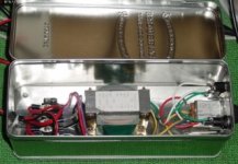
Power chain of connections goes:
Transformer box (nicely shielded and grounded):
- IEC power socket with integrated filtering (had one I pulled from some industrial scrap)
- fuse & switch
- transformer
- terminal plate
* then I have 15v AC wires running ~6ft into a 4-pin DIN MIC plug
Headamp box:
- 2x bridge rectifiers
- (+/-) 680uf 160v pre-regulator smoothing caps
- power LEDs w/resistors
- 7812/7912
- 10,000 uf 25v final smoothing caps
Close to the op-amps for decoupling:
- 47 or 470nf ceramic caps (I think 470nf... should I have used something smaller?)
- 1000uf electrolytics
--------
In the end, it seems the noise is not coming from the transformer stage. I can pull the power interconnect, hear the noisefloor for another half second, then dead silent (while still being able to play audio for ~5 more seconds)... odd. or maybe the regulators are noisy for some reason. Post regulator, the voltage is +12.5, -11.92
Anyway, the R4 (and R6??) change might just be the ticket. Waiting eagerly for your final opinion.
Actually, what would be your best design for using the opa's like this? I do like this higher current dual-mono setup. Lots of punch, with good control, and clips at the point you'd damage your hearing. I'd try the OPA specsheet design, but would just have to make sure to invert the inputs, so the signal goes in the (+)... but wondering if there is an even better design?
Cheers,
bluesmoke
ps, will peek into the chipamp section...
Nordic:
Q: Should only R4 be replaced to the 120R value, or should it be R4 and R6...? Just making sure before attempting a tricky-ish replacement. (I see the opa specsheet shows 200R on both; 120 seems a nice middleground)
also, would it make any difference, if I just threw in a resistor just before the output (would be the easiest fix, but wondering how it could lower sound quality)...
--------
Power chain of connections goes:
Transformer box (nicely shielded and grounded):
- IEC power socket with integrated filtering (had one I pulled from some industrial scrap)
- fuse & switch
- transformer
- terminal plate
* then I have 15v AC wires running ~6ft into a 4-pin DIN MIC plug
Headamp box:
- 2x bridge rectifiers
- (+/-) 680uf 160v pre-regulator smoothing caps
- power LEDs w/resistors
- 7812/7912
- 10,000 uf 25v final smoothing caps
Close to the op-amps for decoupling:
- 47 or 470nf ceramic caps (I think 470nf... should I have used something smaller?)
- 1000uf electrolytics
--------
In the end, it seems the noise is not coming from the transformer stage. I can pull the power interconnect, hear the noisefloor for another half second, then dead silent (while still being able to play audio for ~5 more seconds)... odd. or maybe the regulators are noisy for some reason. Post regulator, the voltage is +12.5, -11.92
Anyway, the R4 (and R6??) change might just be the ticket. Waiting eagerly for your final opinion.
Actually, what would be your best design for using the opa's like this? I do like this higher current dual-mono setup. Lots of punch, with good control, and clips at the point you'd damage your hearing. I'd try the OPA specsheet design, but would just have to make sure to invert the inputs, so the signal goes in the (+)... but wondering if there is an even better design?
Cheers,
bluesmoke
ps, will peek into the chipamp section...
I don't think you want 10,000 uF caps after the regulators. They only need minimal output capacitance to keep from oscillating. Move them in front of the regulators, or remove them entirely (make sure there's a 10uF or so instead). Actually, replace the 680s with the 10,000s and try it.
I just designed a PCB with the same output circuit and have used it before with good results.
I just designed a PCB with the same output circuit and have used it before with good results.
May have some time today to fiddle with the power supply section (need to wait until next week if want to I try the 120R idea (to go to get the parts, if needed).
The plan~!
I'll throw the 10,000uf to pre-regulator and test (leaving the 1000uf decoupling electrolytic caps on the op-amps)... If I notice a any difference, may replace the 1,000's with something smaller.
And away I go~!
The plan~!
I'll throw the 10,000uf to pre-regulator and test (leaving the 1000uf decoupling electrolytic caps on the op-amps)... If I notice a any difference, may replace the 1,000's with something smaller.
And away I go~!
If you piggybacked r5 with a 20k resistor this will change r5 value to effectively 20k as being the path of least resistance. because you made no statement of changing r3 value to 2k to retain the total circuit gain of 12 you would have had a gain of 4 which would change the amplified noise floor.. In my headphone amp i used a series resistor of 15k with a 1.5k shunt to form the voltage divider which sets the gain.. Im not sure about using the 2134 as a buffer, I had tried the ad815 a current feedback op good for up to 200ma continuous output current to buffer an opa637 within the feedback loop and hated the sound big time, no matter what i did it was very cold and clinical and hard sounding. I instead buffered the 637 with a deceptively simple dicreet emitter follower buffer using 1amp 110mhz sanyo devices 2sd600,2sb631 which sounds marvelous.. Nordic is right about the bypass caps 10nf-100nf work well, also I think your electrlytic cap values are insanely high, most power amps dont have, or even need this kind of capacitance. I think you should lower your post ps caps to between 1000-4700mf values and your op decoupling caps to 100mf-220 absolute maximum bypassed with .01-.1m, no need for any more except wasted cash and placing more strain than neccessary on your regulators..
Colin
Colin
BIG EDIT... Changeing those 2 resitors would not affect impendance. you need to add 50 to 120R in series with the output...
I used to use 0.1uf bypass caps with small opamps, but generaly nowadays I stick to 10nf Wima caps, and the keywords are; as close as possible to the pins. Much less "silver" in the sound... it may have as much to do with the type of cap as the size... used 100nf ceramics before (non cg0/np0).
You could try reducing gain a little too.
I didn't look at your shcematic too cloesly, I think I can see enough from the small pic. and the symptoms.
I did see something in the previous post about you haveing made some adjustments. make sure you stuck with original gain... or you may well be listening to an overamplified noise floor.
Don't be scared to experiment, get one thing sorted then move to the next... for a start I would try to get the circuit working on a 9V battery ( has to be very fresh or it will distort worse than anyhthing), this would exlude the PSU, or interaction with, it as a problem.
Also play with other circuits for comparison, you can start with a basic CMOY. Once you figured out a PSU arrangement that works for you, you can stick to it, and only follow the rest of a schematic.. often components connected to power pins are not even shown in schematics.
Also try Rod Elliot's headphone amp.. these sound pretty good.
http://sound.westhost.com/project109.htm You will need 3 opamps for that one though.
http://focus.ti.com/lit/an/sboa031/sboa031.pdf
Have a look at this doc for better understanding of your circuit...
Have a look at this doc for better understanding of your circuit...
Success!
Started 6:30pm Friday... Finished 8am Saturday Morning... (with 2 small food breaks...)
Will report all the specific details as soon as I take lotsa time for lotsa rest, however I ended up doing a little bit of everything. Maybe a picture or two to come...
Cheers, and thanks all!
bluesmoke
Started 6:30pm Friday... Finished 8am Saturday Morning... (with 2 small food breaks...)
Will report all the specific details as soon as I take lotsa time for lotsa rest, however I ended up doing a little bit of everything. Maybe a picture or two to come...
Cheers, and thanks all!
bluesmoke
slept slept slept, still sleepy...
Just one (two? three?) very smallish yes/no/why question(s) before I do a final build report...
(1) On the pre-regulator portion of the power supply I have a 680uf (one on the +, and one on the - rails) right after the bridges, an then 470uf as well on the main board right before the regulator (same 1 each on the + and -). Is this enough? I'm braindead when it comes to smoothing capacitance. Sadly couldn't use my 10,000uf's because they are only rated 16wv (pre-reg is around 20v).
(2) Possibly taboo, but I had also added a single 6800uf attached to the positive and negative rails (skipping the ground) pre-reg... Dumb?? I find it equalizes any offset difference between the two rails. Not considering that the regulators take that job anyway...
(3) Now that things are sounding quite nice. Would I notice any improvement if I popped in a 2227? I've been reading that it has a touch less punch, or limited output, but a more enjoyable sound. Something I'd consider ordering...
Just the final tweaks....
Cheers,
bluesmoke
1 - If it sounds good, it's enough.bluesmoke said:(1) On the pre-regulator portion of the power supply I have a 680uf (one on the +, and one on the - rails) right after the bridges, an then 470uf as well on the main board right before the regulator (same 1 each on the + and -). Is this enough? I'm braindead when it comes to smoothing capacitance. Sadly couldn't use my 10,000uf's because they are only rated 16wv (pre-reg is around 20v).
(2) Possibly taboo, but I had also added a single 6800uf attached to the positive and negative rails (skipping the ground) pre-reg... Dumb?? I find it equalizes any offset difference between the two rails. Not considering that the regulators take that job anyway...
2 - It won't hurt, and I think it would help.
Finished my final batch of tweaking and tinkering (for now I guess... always want to fiddle and fuss)...
Now with an invisible noisefloor, I can actally hear the noisefloor of my CD player (when cranked to max). A good sign. Definitely can hear more definition, or "space" between instruments than most headphone outs I've ever used (mixing consoles, and even some 'audiophile' grade gear). Definitely worth the couple bucks for the parts. May play with some 2227's and 2228's after the holidays just to see if there's any difference. Hopefully someone will give me a few "fun bucks" for christmas.
Still a tiny bit concerned that the opamps aren't decoupled with enough juice. I have 33uf on each opamp power pin, plus 330uf on each rail near the regulator (after the regulator of course). Just power-paranoid I guess. Only seems to distort/clip at deafining levels anyway. Only really there for oscillation prevention as well I guess...
Have taken some pictures, will post them shortly with the wrap-up...
Happy that it just works! (ears ringing)
Thanks again all!
bluesmoke said:
Still a tiny bit concerned that the opamps aren't decoupled with enough juice.
I have 33uf on each opamp power pin, plus 330uf on each rail near the regulator (after the regulator of course).
-----
Just power-paranoid I guess.
-----
Have taken some pictures, will post them shortly with the wrap-up...
Just power-paranoid I guess.
We have quite a number of those here at forum ...
The Snubber Lobby & Black Capacitor Maffia

... guess they do not know enough, yet
... to discuss the actual circuitry and more vital things ...
AndrewT and a little number of other more sensible members
use a more in line with reality approach.
As well as the ever Sound and Reasonable
Rod ESP Elliott
ESP Audio Project Site
99% all info you ever need for Good Audio Designs
=============================================
My own way
I follow the guidelines, the Rule of Thumbs, when making power supply
and decide what ByPass capacitance I will use.
For unregulated:
5-10 uF per mA, max output.
For voltage regulated rails:
1-2 uF per mA, max output.
These both rules will cover bypass of almost every normal audio amplifier circuit.
As in real life - there are always a few exceptions to a rule.
Some very extreme or special circuits may have further demands.
But 90% of those projects we read in this forum, are not in anyway such circuits.
So don't you now get the idea that YOUR CIRCUITS would be so special, and you can't use those TWO Good Rules.
===========================================
===========================================
Quote of The Day:
Just power-paranoid I guess.
===========================================
===========================================
lineup
Overkill, you can do with much less. Plus you should have some small value ceramics right at the pins, electrolytics have a high impedance at higher frequencies, ceramics are better for that.bluesmoke said:...I have 33uf on each opamp power pin, plus 330uf on each rail near the regulator (after the regulator of course).
I'm a happy camper, and will fiddle no more!
Also happy I made someone's quote of the day.
Only bad thing was when I pushed a drill bit under my fingernail, widening a pcb hole. I was doing it manually (with a pin clamp), so luckily had control when I felt something was a bit wrong... Surprisingly no gross damage...
I did put small ceramics very close to the power pins, plus threw on some small film caps while I was reworking the board (leftovers from previous projects). Next build will try using smaller electrolytics next to the opamps (10uf~)... Possibly making every section modular, so I don't have to 'Franken' the board every time I try to tweak something.
Have a feeling the noisefloor problem might have been oscillation, but very non-invasive (not motorboating). or could have been a factor being a gain of 11 (from what I could calculate of the original values; 100k:10k).
Here's the final rundown of the project (sans pictures; still need to dump them):
post transformer bridge board:
(2x)680uf for the (+/-) rails (all I had on hand)
(1x)6800uf connected to the + and - rails, skipping ground
main board:
(2x)470uf pre regulator, on the main board
7815/7915 regulators
(2x)330uf post regulators for the (+/-) rails
audio section main board:
P1= 50k log (Bourns; re-used from my old passive preamp, OK~ for now)
C1= 6.8uf HUGE film caps (will look up the brand (forgot); labeled for audio)
R1= 100k
R2= 1k
R3= 3k
R4 & R6= 50ohm
R5= 20k
on the power pins: (*have to re-check, lost my note)
0.01uf ceramic disc
0.47uf film*
33uf electrolytic
2 power LEDs (1 on each rail pre-regulator. 2k resistor on one, 4k resistor on the other).
Think that's all...!
So now gain seems to be at 7.7~ from what I gather (20k:3k)... more than enough.
Not a hint of noise, and fabulous sound! May change the pot to a 25k when I have the need. Gets super loud by 12:00, and clips soon after, I think mainly due to the fact all my headphones are super low impedance. Wish I had a pair of HD650s to try it with.
Anyway, this was a fun project. Probably because it worked from the start without blowing up parts, and just needed a bit of friendly help to bring it up to spec. Definitely appreciated!
Cheers,
Bluesmoke
... pictures will come!!!
... also will try reading some new books on electronics, as the ones I grew up using in gradeschool were the extremely outdated "boy's guide to electronics" (and teachers being of no help). Radio Shack books also of no help... just had to keep going at things myself until getting a feel for how things worked. Following schematics is easy as pie.
- Status
- This old topic is closed. If you want to reopen this topic, contact a moderator using the "Report Post" button.
- Home
- Amplifiers
- Headphone Systems
- headphone amplifier good and weirdness