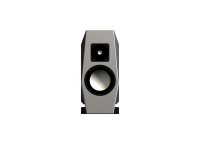
I'm going to use the C95-T6 and C23 in this new project, piano black, white and red(Ferrari). Now I'm working on the x-over.
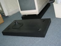
Same idea as the big one, the vent is point downward, air current will lead and twist to horizontal direction by base. Of course it will be setup a backward super tweeter too. An 12 mm aluminium plank will fix on the 36 mm thick front baffle, the whole enclosure wall are 36 mm too. Inside the box are partitioned into a lot of little space like "Matrix", wool damping, silver inner connection...
Same idea as the big one, the vent is point downward, air current will lead and twist to horizontal direction by base. Of course it will be setup a backward super tweeter too. An 12 mm aluminium plank will fix on the 36 mm thick front baffle, the whole enclosure wall are 36 mm too. Inside the box are partitioned into a lot of little space like "Matrix", wool damping, silver inner connection...
Attachments
just a noob here but that space looks a bit thin for any vent over like 1" in diameter. unless youre planning on loading the vent somehow.
something tells me youre going to shoot down my argument with numbers...but gimme a break its not like i can calculate the surface area of the opening without dimensions.
something tells me youre going to shoot down my argument with numbers...but gimme a break its not like i can calculate the surface area of the opening without dimensions.
Looks great. Will be very interested to see the final result.
If the vent is down firing then it will not be possible to simulate the tuning as the air will be impeded, resulting in a shifted tuning and probably aerodynamic problems - chuffing that would not otherwise occur.
Why not put the vent in the front or rear?
If the vent is down firing then it will not be possible to simulate the tuning as the air will be impeded, resulting in a shifted tuning and probably aerodynamic problems - chuffing that would not otherwise occur.
Why not put the vent in the front or rear?
xstephanx said:just a noob here but that space looks a bit thin for any vent over like 1" in diameter. unless youre planning on loading the vent somehow.
something tells me youre going to shoot down my argument with numbers...but gimme a break its not like i can calculate the surface area of the opening without dimensions.
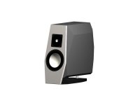
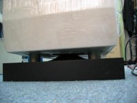
The thin "vent" you mentioned is a aluminium post intended setup to support the weight of the cabinet rear part. The real vent is at the bottom of the main bin like attachment.
Attachments
paulspencer said:As I mentioned, it's still very constrained and a potential problem. You won't know if it is tuned correctly until you build and test it.
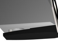
Answer: I know what you're concerning. In my opinion, the gap between bin and base is still a part of the vent, but the rebound of the current from base where opposite to the port(I put it in easy way)will affect the normal reflecting current from the port like you said. To avoid that occur, we must lead the air flow in and out from port to gap very smooth, I setup a cone like the attached photo. I'd measured the impedance, plot is so perfect like textbook, the most important is exactly like what I expected. Why I design the downward reflection? It's a long story, briefly, in my view this sort of structure is more easy to work like a vented box, more easy to adapt the environment of audition, more easy to reproduce a true alike and no directional deep bass.
Attachments

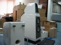
dalcorn said:what are they made of? the white material almost looks like sytrofoam?
The answer to your question is posted in much info already available. Check the posts by our friend fung. There are only about three threads to study on his speaker subject. Research Man, research!
rcavictim said:
The answer to your question is posted in much info already available. Check the posts by our friend fung. There are only about three threads to study on his speaker subject. Research Man, research!
Ah, found what you mean... But the astonishing then about some of the designs I see you guys build is how much geometry you are getting out of HDF/MDF. I purchased 3/4" MDF and managed to get rounded edges but not the extra slants/slopes etc. The detail is mesmorizing (sic).
Do you guys use solid MDF/HDF blocks and carve the design out of it? Or just many individual pieces glued together maybe?
I suppose if I found a pictorial of how to build cabinets like this..... ?
Nice work again Fung.
Reminds me, a little bit, of Tony Gees Cup-a-Soup design:
http://www.humblehomemadehifi.com/Cup-a-Soup.html
Reminds me, a little bit, of Tony Gees Cup-a-Soup design:
http://www.humblehomemadehifi.com/Cup-a-Soup.html
- Status
- This old topic is closed. If you want to reopen this topic, contact a moderator using the "Report Post" button.
- Home
- Loudspeakers
- Multi-Way
- This project is in progress