Phew, everything connected finally... Fuse set to 1.5Amp, powered up with 150W bulb in series - about 75 volts across the transformer primary and 20 volts at unregulated supply output. R0 measures about .6V. So far so good.
Connected directly to the mains (120V across the transformer primary). Fuse blows (1.5A) - a whiff of smoke around the power resitor area (not sure which one). Increase fuse to 2A - switch on - fuse blows again with a whiff of smoke - looks like it is R0 this time. Want to make sure which resistor is heating up - increase fuse to 3A - switch on - R0 & R1 are red hot (quite a bit of smoke) - immediately switch off - looks like they survived. The fuse did not blow up this time.
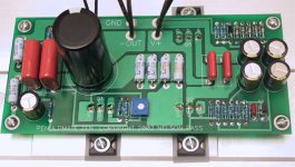
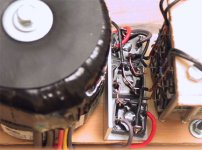
Here is the board picture - discoloration can be seen on R0 & R1. Any help greatly appreciated. Thanks...
Connected directly to the mains (120V across the transformer primary). Fuse blows (1.5A) - a whiff of smoke around the power resitor area (not sure which one). Increase fuse to 2A - switch on - fuse blows again with a whiff of smoke - looks like it is R0 this time. Want to make sure which resistor is heating up - increase fuse to 3A - switch on - R0 & R1 are red hot (quite a bit of smoke) - immediately switch off - looks like they survived. The fuse did not blow up this time.
Here is the board picture - discoloration can be seen on R0 & R1. Any help greatly appreciated. Thanks...
Attachments
From Zen4 article:
If the voltages all check out then you have a 95% chance that everything is proper.If not,it is time do start doing your detective work.This is best done slowly. Wait till the next day.
I took the advice (it was past midnight anyhow). Connected the 150W bulb back in series (fuse set to 1.5A) and switched it on. This time the bulb glows only for the inrush current = open circuit (very small current flowing). Indeed, the primaries are at 125V and unregulated voltage is 50V. The voltages are shown below. Looks like Q2 is blown. I can change it (will have to wait for digikey UPS delivery). But, the question now is: why did it blow at 50V when it was working fine at 20V (what was causing such high bias currents to flow so that R0/R1 will glow redhot). Any ideas? Q3 seems fine with diode tester. R0/R1 measures 1.4ohm. Maybe I should fire up the other channel (with 150W bulb in series) and measure all the voltages rather than just the R0 voltage...
Attachments
Banned
Joined 2002
MikeW said:Are you using IRFP044? They are only rated for 55 volts and you are very close to that. It looks like you did blow up your mosfets. Try IRFP140's. If you need a couple I may have a few. Good luck, Mike.
Well it is showing 54V since there is no load on the transformer. Just fired up the other channel, and all the voltages match up
. The unregulated voltage under load is 48V. Next: mono music from Zen4 after 1 hour of initial burn-in.JasonL said:nice boards im going to perchase a set now for my computer. : O ) ill power a set of nice litte speakers for awsome sound.
Yeah, yeah you can laugh at my expense...atleast you are in a good mood
Banned
Joined 2002
Banned
Joined 2002
This is the message:
Jason, would you mind asking "Jag" to email me Help@passdiy.com, If he has trouble getting the replacement parts I can help. R0 R1 have obviously had too much current pulled through them.
Thanks for the favor.
karen
Jason, would you mind asking "Jag" to email me Help@passdiy.com, If he has trouble getting the replacement parts I can help. R0 R1 have obviously had too much current pulled through them.
Thanks for the favor.
karen
Mono music
One channel works fine (tested with music)...
044 can take upto 50V on regulated, and right now I am getting 40V only on regulated (infact I was using 240 for Q2 when it blew up - part of the passdiy Q-pack, so supply voltage is definitely not a problem). It does look like that heat sinks can take more juice but first I would like to increase the bias current (if at all I do feel the need for more power). To increase supply voltage I will have to get new transformers and I guess that is out of question right now (low on fundage). Thanks for the offer anyhow.
One channel works fine (tested with music)...
MikeW said:I'm glad you got one side working. If you want a couple of 140's for the regulator let me know. Good luck, Mike.
044 can take upto 50V on regulated, and right now I am getting 40V only on regulated (infact I was using 240 for Q2 when it blew up - part of the passdiy Q-pack, so supply voltage is definitely not a problem). It does look like that heat sinks can take more juice but first I would like to increase the bias current (if at all I do feel the need for more power). To increase supply voltage I will have to get new transformers and I guess that is out of question right now (low on fundage). Thanks for the offer anyhow.
bob12345678 said:Jaj,
In the picture of the diode bridges it looks like there are three
bridges I don't follow the need for the third bridge.
regards,
bob12345678
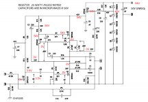
Refer to Zen4 power supply. The third bridge is for grounding.
grataku said:Mike,
I think the mosfets see about 1/2 of the PS volatege each which, for the 044 is well within the operating V, so no need to switch.
The problem is why does Jag have 54 v after the regulator and even more importantly why do 54 volts show up at the gate of output CSS?
Here is a quote from Zen4 article:
"If you manage to cool the amplifier very well,you can consider whether you can get more power out of it. I would say the practical limit to this will be Q1,which is run at about 44 watts with the 2 amp bias.Personally,I hesitate to operate this device at greater than 50 watts,but you can crank the supply voltage and bias up
higher if you want. With the IRFP044 I would not exceed 50 volts on the regulated supply. If you want to try higher,I suggest the IRF140 or 240 devices."
As far as voltages in the picture are concerned, I can think of 2 things. I am not sure how a MOSFET fails, but it is possible that the Q2 is blown and will not conduct with even 54V at the gate. Or, R0/R1 are blown and will not let any bias current go through no matter how hard the Q2 tries. Expert comments required
None of these 2 scenarios still tell me why anything should blow in the first place.
I´m not an expert, but things like this happend to me too when building my V4. Measure if R0 and R1 are OK - i blew some.
Check Q2 and Q5. I´m sure they are blown.
Are all the other parts really looking ok?
You should take a close look at the regulator area - R17 / 18 Z1 D1 - is there still 54V after take Q5 away?
If R0 and R1 are blown, put in new Q´s and only one of R1 R0 for testing.
there are some threads on problem like this:
http://www.diyaudio.com/forums/showthread.php?s=&threadid=6971
http://www.diyaudio.com/forums/showthread.php?s=&threadid=7335
jag said:As far as voltages in the picture are concerned, I can think of 2 things. I am not sure how a MOSFET fails, but it is possible that the Q2 is blown and will not conduct with even 54V at the gate. Or, R0/R1 are blown and will not let any bias current go through no matter how hard the Q2 tries. Expert comments required
On second thoughts it is not possible that Q2 is okay but R0/R1 are blown since there would be voltage on Q2 source. I think that Q2 is most definitely blown. What else, I am not sure. But what was causing the high bias currents for Q2 to blow in the first place, I still do not know

till said:I´m not an expert, but things like this happend to me too when building my V4. Measure if R0 and R1 are OK - i blew some.
Check Q2 and Q5. I´m sure they are blown.
Are all the other parts really looking ok?
You should take a close look at the regulator area - R17 / 18 Z1 D1 - is there still 54V after take Q5 away?
If R0 and R1 are blown, put in new Q´s and only one of R1 R0 for testing.
there are some threads on problem like this:
http://www.diyaudio.com/forums/showthread.php?s=&threadid=6971
http://www.diyaudio.com/forums/showthread.php?s=&threadid=7335
I think too that Q2 is blown. How do I check for a working/blown MOSFET? Do I have to pull it out of the PCB? And the biggest question of all - why the high bias current in the first place to blow it? Thanks for your input.
I tested them in the same way as descibed in "matching mosfets"
look here:http://www.diyaudio.com/forums/showthread.php?s=&threadid=6971
I think you have to pull them out of the PCB, but i´m sure they are blown if your voltage figures you posted are right. So take care on not to damage the PCB and forget about the Fet´s they are´nt that expensive like PCB´s.
If inital Bias current was too high, the current source FET did´n limit Bias current because there´s something wrong around the npn, the resistores around the npn, and the gate of current source FET. Check on the PCB, measure.
- Status
- This old topic is closed. If you want to reopen this topic, contact a moderator using the "Report Post" button.
- Home
- Amplifiers
- Pass Labs
- HELP: Zen V4 blowing fuse (and smoke as well)