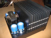
Here are two newly completed 100 watt Aleph-X monoblocks. The project started back when the Aleph-X thread was in full swing. Most of the time has been spent gathering parts and getting sidetracked on other things. The actual building took place over the past 4 months.
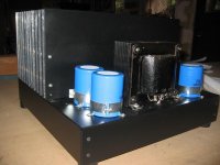
The units are built on 17" x 17" x 3" inch Bud chassis and weigh 64lbs each. The heatsinks are .187 5052 aluminum sheet stock from onlinemetals.com that has been sliced and diced on a table saw into 17" x 8" plates each of which takes two IRFP240's. 5052 is the cheapest stuff they sell. The center ten plates (of 12) hold the 20 output transistors. The front and rear plates are not part of the heatsink but are present to insure that the center ten plates have an approximately equal thermal environment in terms of convection and radiation patterns. These two plates are .125" thick (because I had some of this on hand). Only the front of the front plate, the rear of the rear plate and all the edges are painted. All other heat sink surfaces are left natural. The plates are connected with 6-32 threaded rod from the local hardware store and the separators are 3/4" unthreaded standoffs out of the Digikey catalog. The 240's all run within a degree or two of each other. The bottom of amp is open and there are two large rectangular cutouts in the chassis under the power transistors to allow air to flow up into the heatsink. The heatsink assembly alone weighs over 30 lbs.
I admit that this all yields a very ugly looking amplifier. However, you end up with a result that performs as well as any other with minimal time and money spent.
The amplifiers are painted with black satin enamel primarily because Mrs. GL put her foot down regarding the use (again) of natural aluminum amplifiers in the listening room. Search for the "DIY heatsink" thread to see an example of this type of construction in "natural".
Virtually everything in the amps came from readily available sources (in the US) like Mouser, Digikey, onlinemetals, and Madisound. The PS caps are stubbies from the BGMicro sale at $3.00 each. The transformers are Signal 88-8's out of the junk box. Various bits and pieces like capacitor clamps, connectors, and miscellaneous hardware came from the junk box too.
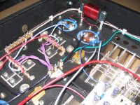
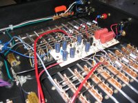
Construction of the circuitry is symmetrical - both on the perf board as well as for the output section wiring.
The original plan was to build 150-160 watt versions using 24 output devices. The total heat load for the room would have been 1100-1200 watts. For that much heat budget I figured I could build four 100 watt units, then biamp, and have 400 watts of effective output power available for each speaker.
With 500ma of bias per output device and with the amp on it's side on the bench (a thermally suboptimal orientation), the heatsinks rise to a temperature 21C above ambient measured at the edge of the plates directly above the transistors. This was better than I had hoped for. V1 and V3 have since been replaced with fixed resistors and the bias increased to 540ma per device (115W @ 8 ohms). After the amps are running right side up with their feet on so that convection cooling is optimized, I will see how things go and maybe turn the bias up to 600ma. Unfortunately that increases the total amount of heat being dumped into the room. Class A - you've gotta love it.
Relative offset is less than 50mv right from turn-on. It typically settles to less than 3mV on one amp and less than 10mV on the other. Absolute offset, however, starts at 3v and settles to less than 1.5v within ten seconds. It then begins a slow decline to somewhere less than .7V after an hour - but its still dropping very slowly. It feels like I'm going to have to leave the amps on for several days to find the ultimate best point for this adjustment.
I have listened to the amps on and off what with adjustments for maybe 4 hours and only 2 hours at full operating temp with the CCS's adjusted to 50%. At this point I can only say that they sound just wonderful. The sound is pure and clean up to very high levels. They resolve low level detail and create three dimensional spaces better than anything I've heard. There is no hum or noise even with my ear next to the loudspeaker. A fantastic amplifier. Do I sound jazzed? Well, I am.
I would like to thank Nelson Pass for his support and generosity and Grey Rollins and everyone else who contributed to the Aleph-X thread and WIKI. I would also like to say a special thank you to those people who have built this circuit and who have regularly and faithfully provided advice and encouragement to new builders.
Regards,
Graeme L.
The units are built on 17" x 17" x 3" inch Bud chassis and weigh 64lbs each. The heatsinks are .187 5052 aluminum sheet stock from onlinemetals.com that has been sliced and diced on a table saw into 17" x 8" plates each of which takes two IRFP240's. 5052 is the cheapest stuff they sell. The center ten plates (of 12) hold the 20 output transistors. The front and rear plates are not part of the heatsink but are present to insure that the center ten plates have an approximately equal thermal environment in terms of convection and radiation patterns. These two plates are .125" thick (because I had some of this on hand). Only the front of the front plate, the rear of the rear plate and all the edges are painted. All other heat sink surfaces are left natural. The plates are connected with 6-32 threaded rod from the local hardware store and the separators are 3/4" unthreaded standoffs out of the Digikey catalog. The 240's all run within a degree or two of each other. The bottom of amp is open and there are two large rectangular cutouts in the chassis under the power transistors to allow air to flow up into the heatsink. The heatsink assembly alone weighs over 30 lbs.
I admit that this all yields a very ugly looking amplifier. However, you end up with a result that performs as well as any other with minimal time and money spent.
The amplifiers are painted with black satin enamel primarily because Mrs. GL put her foot down regarding the use (again) of natural aluminum amplifiers in the listening room. Search for the "DIY heatsink" thread to see an example of this type of construction in "natural".
Virtually everything in the amps came from readily available sources (in the US) like Mouser, Digikey, onlinemetals, and Madisound. The PS caps are stubbies from the BGMicro sale at $3.00 each. The transformers are Signal 88-8's out of the junk box. Various bits and pieces like capacitor clamps, connectors, and miscellaneous hardware came from the junk box too.
Construction of the circuitry is symmetrical - both on the perf board as well as for the output section wiring.
The original plan was to build 150-160 watt versions using 24 output devices. The total heat load for the room would have been 1100-1200 watts. For that much heat budget I figured I could build four 100 watt units, then biamp, and have 400 watts of effective output power available for each speaker.
With 500ma of bias per output device and with the amp on it's side on the bench (a thermally suboptimal orientation), the heatsinks rise to a temperature 21C above ambient measured at the edge of the plates directly above the transistors. This was better than I had hoped for. V1 and V3 have since been replaced with fixed resistors and the bias increased to 540ma per device (115W @ 8 ohms). After the amps are running right side up with their feet on so that convection cooling is optimized, I will see how things go and maybe turn the bias up to 600ma. Unfortunately that increases the total amount of heat being dumped into the room. Class A - you've gotta love it.
Relative offset is less than 50mv right from turn-on. It typically settles to less than 3mV on one amp and less than 10mV on the other. Absolute offset, however, starts at 3v and settles to less than 1.5v within ten seconds. It then begins a slow decline to somewhere less than .7V after an hour - but its still dropping very slowly. It feels like I'm going to have to leave the amps on for several days to find the ultimate best point for this adjustment.
I have listened to the amps on and off what with adjustments for maybe 4 hours and only 2 hours at full operating temp with the CCS's adjusted to 50%. At this point I can only say that they sound just wonderful. The sound is pure and clean up to very high levels. They resolve low level detail and create three dimensional spaces better than anything I've heard. There is no hum or noise even with my ear next to the loudspeaker. A fantastic amplifier. Do I sound jazzed? Well, I am.
I would like to thank Nelson Pass for his support and generosity and Grey Rollins and everyone else who contributed to the Aleph-X thread and WIKI. I would also like to say a special thank you to those people who have built this circuit and who have regularly and faithfully provided advice and encouragement to new builders.
Regards,
Graeme L.
Attachments
Here is the schematic.
The circuit is essentially the original Aleph-X as shown in the schematic at the beginning of the Aleph-X thread. I have retained the original part numbering. All of the changes made have been discussed by others at various times in various threads. There is nothing new here. The original circuit has simply been reworked to provide an amplifier appropriate to a specific requirement.
The following changes were made:
1) Rail voltages were increased to about 26 - 27V. The CLC type supply uses 68KuF/50V - 1mH - 68KuF/50V filters on each rail. The inductors are Madisound Sledgehammers. Yes they probably are saturating - but they look so cool. There is a great deal of discussion on the Aleph-X thread about sagging transformer secondary voltages under heavy load. I did not experience this. The transformers have a slight soft buzz that's only audible up close.
2) The output device complement was changed to 20 IRFP240's per monoblock or 5 transistors per quadrant and bias was initially set to .5 amps per transistor for a total of 5 amps. These were matched to within .01V in sets of 10.
3) Output source resistors were set to 1 ohm @ 1% to help equalize the dissipation on each output transistor because of the separate heatsink plates. They are 2W Ohmite NI wirewound types chosen because they were one of the better and less expensive units in the catalogs.
4) The CCS sense resistors R2, R3, R42, and R43 were changed to .47 ohms because I had a pile of them. Extra resistors r50, R51, R52, R53, R54, and R55 were added.
5) R16 and R30 were changed to 220K to give a gain of 26dB with a balanced input.
6) Pots V1 and V3 were adjusted and then they and the original 47K resistors were swapped for single fixed values. 82K gives 500ma of bias per device @ 13W of dissipation. 100K gives 540ma per device.
7) R12 and R34 were adjusted for 50% CCS AC current gain. I used the NP method given in the Aleph-X builders thread. First, 475 ohm resistors with 1K pots in series were substituted for R12 and R34. R12 and R34 were then disconnected and with a 100Hz sine wave input the AC voltage across R6 and R41 was measured. R12 and R34 were then reconnected and the pots adjusted so that the AC voltage across R6 and R41 drops to half it's former value. The R12 and R34 pot/resistor networks were removed and measured and fixed resistors substituted. The measured value was 853 ohms and I created this with 634 ohms + 221 ohms which I had on hand, otherwise the closest 1% value is 845 ohms.
When NP describes this process he states that the input level should be set to give 16VRMS across an output load resistor. I couldn't get anywhere near this value without serious clipping. The highest unclipped value I could get was 12V measured with an AC voltmeter. At first I thought something was wrong because this appeared to be way too low. But after I thought about it I figured that with a rail to rail voltage difference of 54V I would start seeing clipping at 48V under ideal circumstances. With the CCS gain at zero I would lose 50% of the current at clipping so the clipping point drops by half. Add to that I was using an unbalanced input so half again. So 12V output at clipping was probably correct.
8) 4.75K MacMillan resistors were added. This resistor value is for me the one big mystery in the circuit. Like it says in the WIKI this value is traded off against the value of the output grounding resistors. Common mode performance is traded off against DC offset performance.
If I had the opportunity to request one breadcrumb from NP it would be the corresponding MacMillan values for the 100 ohm output resistors in the XA series.
9) Several other resistor values were changed in accordance with NP breadcrumbs scattered around in the Aleph-X and Aleph-X builders thread.
10) R21 was deleted.
11) R14, R17, and R31 were increased because of the higher rail voltages.
12) 4.7uF PP input caps and 100K resistors were added to the inputs.
13) 220uF caps were added to each rail on the PCB. A 4.7uF cap was added across D1. These changes were made because similar parts appear in the photos of the XA160 and XA200 that have been posted here or included in various magazine reviews.
14) The rectifier bridges are individual IXYS FRED type soft recovery diodes. There are two bridges in each amp for the two center tapped transformer secondary windings. The outputs of the bridges are paralleled at the first filter cap. This seems to work fine.
Whenever possible individual ground wires were run to a single star ground. There are three ground connections to the PCB: one to each group of input (+ and -) related grounds and a third which collects the power supply connections including the CCS. The RCA jack is insulated from the chassis and its ground pin is connected to pin 3 of the XLR and then pin 3 of the XLR has a separate wire back to the star ground. The star ground is connected to a frame ground (near the IEC inlet) through a CL60. The IEC inlet ground is connected to the frame ground.
I copied the input filtering scheme from the Aleph 60 more or less. Next time I will buy a filtered inlet regardless of what it costs!
I hope that some of this information is helpful to the next builder. If anyone sees anything wrong here please post.
Regards,
Graeme L.
Attachments
Hi David,
Thank you. I've used this method for years. With 5A of bias the heatsink temperature rise over ambient is 21C. When you're working in a garage that has an ambient of 7C these make great hand warmers. In the listening room and with 5.4A of bias the sinks are quite warm but not hot or even uncomfortable.
Graeme

Hi Graeme. That is impressive work you did on the A-X") Studying the pics, reveals the work of a true craftsman Very nice built indeed. You just gotta love the "tube-like" impression.
Studying the pics, reveals the work of a true craftsman Very nice built indeed. You just gotta love the "tube-like" impression.
Nice way of heatsinking.
Also the measured performance is pretty nice. The minimal DC offset is very good. Congrats
Steen
Studying the pics, reveals the work of a true craftsman Very nice built indeed. You just gotta love the "tube-like" impression.Nice way of heatsinking.
Also the measured performance is pretty nice. The minimal DC offset is very good. Congrats
Steen
Hi mpmarino and Steen,
Thank you for your comments. I see the resemblance. These have actually replaced a 115W per channel tube amp in my system. They do indeed sound very similar to that tube amp but with better detail. They don't throw as big an image but the image they present sounds more "correct". Anyway they're still breaking in and sounding better every day. We'll see how it goes.
Cheers,
Graeme
aleph 100x
GL pretty impressive, did you use the pc board that was part of the x thread? Looks like you did pt. to pt. If you used the board where did you get it? I built the alpeh 1.2's using pt to pt wiring.
Just takes a bit longer. Your pictures are insipiring me to attemp this project. dave
GL pretty impressive, did you use the pc board that was part of the x thread? Looks like you did pt. to pt. If you used the board where did you get it? I built the alpeh 1.2's using pt to pt wiring.
Just takes a bit longer. Your pictures are insipiring me to attemp this project. dave
Hi John.
How is that new room of yours going.
This is one of the best diy X Aleph implementations I have seen and I propose to update my X Aleph along these lines.
20 IRFP240's is a good number.
I etched a pair of your boards diy style yesterday in anticipation!
(As much as I like my summer (ska) amp, its not nearly as much fun as diy class A SE)
Ian
Hey Ian!
Long time, no see.
At the risk of hijacking this thread: (sorry)
My media room is rather interesting. I've installed a twelve foot by seven foot Dalite projection screen (3.6 meters x 2.1 meters) and slam it with an anamorphic lens/Infocus X1 (the one with the Farouja process). Great introduction to front projection at a very reasonable price--costs less than a 1.5 meter plasma by at least half. HUGE picture! I've purchased three Hafler amps on Ebay to drive my horns, bass horn included (similar to Nelson's Klein, but front loaded with LAB 12s).
I lost one channel on my Ax (motorboating) so I use the other channel for my center speakers (7.1). I've constructed a couple of twelve foot (3.6 meter) transmission lines using a pair of LAB 12 drivers in each and placed them a meter behind the sofa. BIG first octave!
I have plenty of the original AX pcbs left. If you need a pair, just holler.
I'm gathering materials to construct an Aleph 30 (Peter's pcb and resistors and my unused, massive chassis--I once posted a pic of it. It was for the Aleph 2s.
So, here I am hanging out at the big AX page. Someday, I've got to build me one of these brutes.
Nice chatting,
John
Hi Dave,
Yes this is just simple point-to point wiring on the perf board. The board material is a better grade of phenolic and is made by Vero. I don't have a part number. It came out of the junk box. If I had purchased the material I would have bought one of their FR4 versions instead. It's better material. Mouser and Digikey both carry the Vero products I believe. The layout of the parts on the perf board was my own.
I am glad you were inspired by the pictures. That's why I posted them. I was encouraged by other pople here so I'm very happy to give some of that back.
Hi John,
My original intent was to put a 40mm 12V fan in the middle of the front of the chassis, then seal the chassis, and run the fan at 9V into the resulting plenum. It was a Pabst 612-something which had a noise figure of 16-17dBA. I ended up not using it. The air noise was inaudible but there was still a higher pitched buzz that sounded like commutating noise that I couldn't get rid of. I was going to use the fan control circuit NP published here a short while ago.
Hi Ian,
Thank you for your kind words. Frankly your posts have a significant part of the inspiration for these amps. Did you stick with the your original 4.7K MacMillan resistor values? I am thinking of increasing the value to 10K or even 22K to see what happens. Any thoughts? I recall that you also added input coupling caps to your Aleph-X but never published an updated schematic. How does what you did compare to what I did? Thanks very much.
Cheers to everyone,
Graeme
Hi Graeme,
I'll take a pat on the head any day but you got the wrong Ian.
Try sending the other famous "Ian" a message via his profile to answer your questions!
If you search back in the first 50 or so pages of Grey Rollins original thread we tried other values and 4.7 K seems about optimum. The Load resisters (30-100R) also help to stabalise the DC.
Ian Mackenzie (Macka)
Hi Ian,
Sorry about that. In fact this may not be the first time I've made this mistake. You're perfectly welcome to keep the pat on the head by the way. Thanks for the reply.
I remember smaller values being tried - e.g. 2.2K and 1K - but I don't recall people trying larger values. And I really don't remember that anyone actually "listened" to other values to see if the sound was affected.
Graeme
Prompted by Ians comments above, I decided to do more work on finding the optimal value for the MacMillan resistors in my Aleph-X's . Over the years NP has given out factory values for several of the parts on Greys original schematic but the value for the MacMillan resistors isn't one of them. I am going to assume that people reading this post know where these resistors are in the Aleph-X and what they do. My Aleph-X' were built with a value of 4.75K.
I started this quest by reviewing the first 100 pages of the big Aleph-X thread which was a good thing because I found some information I had missed.
My summarized findings are:
1) NP refers to these parts as one of several ways to control absolute DC offset performance. No one way is seen as the best and he appears to recommend a balance of all methods. These include close matching of parts, load resistors from the output nodes to ground, and the MacMillan resistors.
2) The MacMillan resistors are not required. Grey Rollins original circuit did not include them. However, he had to use a fairly low value of 30 ohms for the output load resistors in order to achieve a level of absolute DC offset control he could live with.
3) NP states in a post somewhere around page 58 that the MacMillan resistors could be as low as 5K without things "going to hell". A few members tried 1K and 2K resistors and seemed happy with the results. So what is meant by "goes to hell"? These resistors provide feedback to the diff pair sources and as the value drops the common mode performance of the amplifier suffers. The big question is - does the sound of the amp suffer?
Clearly, the only thing to do was try some differnet values and 1) listen to the amps and 2) measure the absolute DC offset performance. The worst case range range of possible resistor values was infinity at the high end and 5K at the low end. I figured from NP's remark about 5K that 10K would be a more reasonable "lowest" value.
The first value tried was 22K. The relative DC offset performance was fine. The absolute DC offset to a long time to settle - like an hour or more and even then it wandered seemingly with a mind of its own over a range of 1 to 1.5 volts. The sound, however, improved dramatically over the origina 4.75K resistors. A tightness and constriction in the sound disappeared and the music became more dynamic and relaxed. The sense of space improved. And I'm pretty certain the low bass performance below 30Hz improved as well. As a maggie user this last point is a big deal.
I decided that next I would try decreasing the value instead of increasing it - so 10K's went in. Again the relative DC offset performance was fine. Almost all of the improvement in the sound remained. This is a tough call, by the way, because you need to give the amps a long time to heat back up to operating temp before seriously listening. The absolute DC performance was more controlled - starting out at 8 - 9 volts and settling to 5 - 6 volts after 5 minutes. It then took another 45 minutes to settle down to below a volt. Any wandering was small and tolerable. In the end this is where I have decided to leave things for now.
Has anyone else done any similar experiments and listening tests? If so could you please add your findings. I would really appreciate any feedback from anyone. Thank you.
Regards,
Graeme
Interesting observations.
I can only think that careful matching of the input pair and both halfs of the negative side would help with offset issues.
30 ohms is not a hell of a lot in the scheme of things anyways.
I plan to re engineer my X Aleph along your lines soon and will post my impressions and measurements.
Ian
I can only think that careful matching of the input pair and both halfs of the negative side would help with offset issues.
30 ohms is not a hell of a lot in the scheme of things anyways.
I plan to re engineer my X Aleph along your lines soon and will post my impressions and measurements.
Ian
- Status
- This old topic is closed. If you want to reopen this topic, contact a moderator using the "Report Post" button.
- Home
- Amplifiers
- Pass Labs
- AX100 100W Aleph-X Monoblocks