I was looking at the Acorn ESL kit from ER Audio and was intrigued by this from their web site:
As with the ESL III, it was considered essential to make this speaker a zero shunt capacitance design.
As an example, ESL panels, which have air gap spacers that are simply glued onto a conductive stator, may be simple to build but there is a serious trade-off. The area of grid that has the spacer covering it is non productive - it cannot drive the diaphragm, BUT the amplifier is still driving the capacitance it presents.
I wanted to see if their style of insulator construction could be done DIY. They use an acrylic sheet that has the cutouts CNC machined. Not an option for me, but I hit on the idea of stacking two thinner acrylic sheets to achieve the same result.
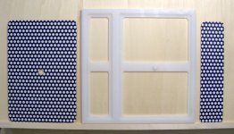
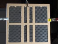
The photo below shows my small two-way proof of concept insulator. It would needed to be scaled up in length for an actual ESL and two mirror image insulators would be needed for a complete panel. It's two layers of 0.100" thick white acrylic glued together which should give a diaphragm to stator distance of 0.056" when used with 0.036" thick perforated steel sheets, allowing 0.005" for powder coat thickness. The stators shown are not the real thing, they're printed on cardboard for this test.")
Note the round plastic peg on the horizontal insulator and the hole to clear it in the perforated stator. They're the 'node points' refered to by ER Audio. I believe the peg should have holes for a screws to connect both halves of the ESL panel.
As with the ESL III, it was considered essential to make this speaker a zero shunt capacitance design.
As an example, ESL panels, which have air gap spacers that are simply glued onto a conductive stator, may be simple to build but there is a serious trade-off. The area of grid that has the spacer covering it is non productive - it cannot drive the diaphragm, BUT the amplifier is still driving the capacitance it presents.
I wanted to see if their style of insulator construction could be done DIY. They use an acrylic sheet that has the cutouts CNC machined. Not an option for me, but I hit on the idea of stacking two thinner acrylic sheets to achieve the same result.
The photo below shows my small two-way proof of concept insulator. It would needed to be scaled up in length for an actual ESL and two mirror image insulators would be needed for a complete panel. It's two layers of 0.100" thick white acrylic glued together which should give a diaphragm to stator distance of 0.056" when used with 0.036" thick perforated steel sheets, allowing 0.005" for powder coat thickness. The stators shown are not the real thing, they're printed on cardboard for this test.
Note the round plastic peg on the horizontal insulator and the hole to clear it in the perforated stator. They're the 'node points' refered to by ER Audio. I believe the peg should have holes for a screws to connect both halves of the ESL panel.
Attachments
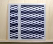
Here's the diaphragm-side view with the stators in place. I'm thinking epoxy adhesive would work to hold the stators in place. Rough up the acrylic with sandpaper, set the stators in with some weights to hold them flat, and pour the epoxy into the holes of the stator.
Attachments
Bill
I've been thinking of a similar design using egg crate light diffusers
removing cells to create a window but leaving in a row of cells
every 4" or so for support of the perforated stator.
But your design looks simply elegant.
Here's a link to an off-set design using wire:
http://mdarling.tripod.com/xencat.html
I've heard there's been discussions of using silicon dots
for damping similar to the nodes you mention, in the
Dutch forum.
Is your tweeter segment going to be electrically separate?
Is your stator diaphragm spacing going to be the same
in the tweeter segment or would it be better with less spacing?
Lucius
Hi, Lucius
I'd appreciate any ideas on what the correct spacing should be for the stators to diaphragm. The ESLs will be used from probably 300 HZ on up with the bottom end filled in with transmission line woofers.
From the Xencat site: There is no reason to justify using perforated aluminum if terms such as quick and easy are to be headlined as design criteria. This is simply a second rate way to build an ESL.
Hmmm, I'm not sure what to make of that statement.
Yes, as I read more about ESLs, there seems to good reasons to go with two or three electrically separated sections. Polar response and power handling are two that come to mind.Is your tweeter segment going to be electrically separate?
That's one area where the ER Audio Acorns are better. Their CNC machining of the insulators allows them to use different spacings, while my method will not as shown. I think it could be done by using thin spacers between the insulator and stator when gluing the tweeter stators in. It's something I still have to look into.Is your stator diaphragm spacing going to be the same
in the tweeter segment or would it be better with less spacing?
I'd appreciate any ideas on what the correct spacing should be for the stators to diaphragm. The ESLs will be used from probably 300 HZ on up with the bottom end filled in with transmission line woofers.
Thanks, I hadn't seen that one before. Is it just me or is the site missing pictures?Here's a link to an off-set design using wire: http://mdarling.tripod.com/xencat.html
From the Xencat site: There is no reason to justify using perforated aluminum if terms such as quick and easy are to be headlined as design criteria. This is simply a second rate way to build an ESL.
Hmmm, I'm not sure what to make of that statement.
That's some very nice work there! I thank you for reminding me of yet another reason to make a router table!
That stator design is not without precedent. Quad uses a similar technique in the ESL-63. They use perforated PCB as the stator, and glue it to a plastic grid. The edges of the grid are stepped and provide the attachment for the diaphragm.
Quad leaves the edge of the stator some distance from the diaphragm support, so if a piece of dust or a bug finds its way into the speaker, it won't always get trapped between the diaphragm and stator. You might consider such a thing before your final build. Also, you should consider providing for dust covers, either on each driver or a single cover that covers the entire speaker.
You will find that epoxy will not bond well with acrylic. There are contact cements that work well for bonding the metal to the acrylic and bond the diaphragm to the acrylic. The trick will be to find a distributor who well sell you a small quantity of the stuff- it is made for industrial use.
I_F
I don't recall the exact spacing but I believe it is 1.5-2 mm from the diaphragm to each stator in the ESL-63.
Thanks, I_Forgot.
I did these pieces on a router table with a fence to get the straight lines and a piece of paper glued to the acrylic with the openings drawn on it.
If I did it on a larger scale, I'd use a plywood template with rectangular cutouts and a guide bushing in the router base, routing freehand against the template. I've used that method for doing rectangular port cutouts and cutting the recess for flush mounting pincushion frame speakers. With an accurate template, the results look great.
Would the grille fabric count as a dust cover, or would I need another cover?Also, you should consider providing for dust covers, either on each driver or a single cover that covers the entire speaker.
Fabric won't keep dust out, and may even add some of its own fuzz. You will want to use the same material you use for the diaphragm, so get a lot more than you think you need. You will need to tension dust cover(s) because if there are any wrinkles in them they will rattle and buzz whenever the speaker plays a bass note. The tension isn't as critical as it is for the diaphragm, so you can just use a heat gun to shrink the wrinkles out of the film.
I_F
I_F
The dust cover seems like a very good idea and would be easy to add to the stacked insulator.
Have you used the dust covers and do they change the sound at all? I've only seem them once before in Dayton Wright ESLs.
I've got 10m of 795mm wide, 6 micron mylar to work with.
Have you used the dust covers and do they change the sound at all? I've only seem them once before in Dayton Wright ESLs.
I've got 10m of 795mm wide, 6 micron mylar to work with.
Quad ESL-63s use dust covers that cover the whole speaker on the front and rear sides. There is no apparent effect on the sound, though the Quads trap a large volume of air between the dust covers and drivers. The large area of the dust cover and relatively low tension result in low resonance frequencies.
If the dust covers were mounted on individual drivers, close to the stators, there would be much less air trapped, so the air that is trapped may start to look like extra mass on the diaphragm. Also, the dust cover would have its own resonance at a frequency a bit lower than the diaphragm due to lower tension. It's hard to say if any of that is going to matter. Try it and see...
I_F
For anyone that is not familiar with ESL dust covers, here's what they look like and how to replace them on a Quad ESL.
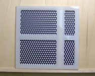
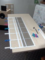
I'm going ahead and using the stacked insulators for my ESL speakers. The background of the picture below shows the outer insulator after routing, with the perforated steel stators held temporarily in place. The acrylic is 0.118" thick, white, and measures 13-3/4" wide x 37-1/16" high.
You can see the router jig in the foreground. The base is a 2' x 4' sheet of 3/4" chipboard. On the left side is two of the three dowels that locate the acrylic blank and the routing template. Four flat head screws hold everything together. The acrylic sheet gets sandwiched between the base and template.
It worked out quite well. I cut four identical insulators using a 1/4" two-flute carbide router bit and a guide collar on the base of the router. It took about 60 minutes to rout each insulator.
Attachments
This picture shows the second layer of 0.100" acrylic being glued to the base layer of 0.118" (3mm) acrylic. It's hard to see, but there's three 1/4" wide strips glued to the center ribs and a 1/2" wide border around the outside of the base layer. All held together with Weld-on #3 solvent cement.
Attachments
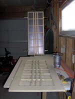
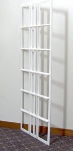
Thanks, dstockwell. It's been a long time between updates, but the insulators are done. I've attached a photo that shows one of the panels with 0.250" thick x 0.563" stiffeners glued on edge to the main panel. Two panels held together are incredibly stiff when I try to flex them in the middle.
The perforated steel stators should be powder coated next week.
BillH
The perforated steel stators should be powder coated next week.
BillH
Attachments
The perforated steel stators should be powder coated next week.
What kind of powder coating will you use?
Good looking project by the way...
Thanks, Brian. I'll be using Tiger 2100 Series 49 polyester/TGIC, white (11500) in color. Tiger .pdf Datasheet.
Check The ESL Build Thread for more info about the whole ESL system.
Check The ESL Build Thread for more info about the whole ESL system.
Bill,
The reason I asked about the powder coating is that it needs to be slightly conductive for the ESL to work, as you may well know. Acoustats' James Strickland wrote about this many years ago. For example, if you could somehow thoroughly coat Teflon onto the stators, the Teflon dielectric would steal all of the electric field away from the air gap. The coating needs to "leak" enough to bring the stators' electric field out to the gap. It doesn't need to be very conductive, only when compared to the air gap itself. For example, Martin Logan's black finish is probably carbon-loaded to make it slightly conductive, but not enough to pose a shock hazard if touched. Your material is probably going to be OK, but I didn't see an electrical conductivity spec.
Keep us posted as this project progresses.
Brian, I couldn't find any electrical specs for the powder coat either. I'm hoping it will work. It's the only type I have available and didn't realize it had to be 'leaky'. Thanks for the info.
I've sent an email to the manufacturer of the powder to see if they can give me any numbers.
I've sent an email to the manufacturer of the powder to see if they can give me any numbers.
- Status
- This old topic is closed. If you want to reopen this topic, contact a moderator using the "Report Post" button.
- Home
- Loudspeakers
- Planars & Exotics
- Stacked Acrylic ESL Insulator