There have been many threads on active x-overs. I wonder how many of those who have suggested one type of crossover or the other have critically listened to the suggested crossovers versus others. Not to undermine anybody's credibility but a genuine doubt arises when subtractive crossovers are preferred to simpler forms like 2nd order LR.
I have listened to many types of crossovers and orders and have found that each of them are certainly not short of faults. In my opinion the 4th order subtractive crossovers which use All Pass delay networks for linear phase at the output, are the worst sonically. The cut-off profile is nevertheless good and oscilloscope shots leave very little to be desired; however, sonically they cause a blur in the midrange and the transient response plus definition in the bass region is very poor. I think that this is due to higher group delay. The ones that use Low Pass Filters as the active elements before subtraction are the worst offenders.
There are those that use cascaded 1st order High Pass Networks to obtain a 4th order x-over, but the bass suffers quite a bit in these types.
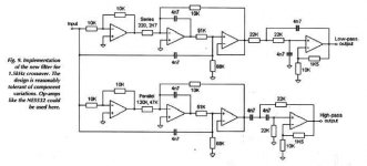
Sometime ago Electronics World published an article entitled "Precise Active X-over". I have referred to this in past threads. I am posting the schematic as an attachment. In my opinion, this is one of the best crossovers sonically. I have configured the orginal two way into three way by duplicating the two way network at the output of the High/Low output. I preferred to tap off the Low output to the Amp, but pass the High output through another two way network to obtain Mid and High outputs. This has been critically tested in domestic environments with highly satisfactory results. The real test for all of the networks mentioned above have been in Professional Audio outdoor work, where 18" drivers are used in Horn-loaded Bass Bins, 12"/10" drivers in Mid Horns and Horn Tweeters are used. The blur in the mids or the slight lack of transients in the bass is all too evident then.
One could improve on the active elements used in the crossover. The schematic shows the NE5532s. I have tested various op-amps including OPA2604s. Each do have a sonic signature. My idea is to try out discrete op-amps, as illustrated in the Passlabs site and use higher operational voltage to avoid a bottleneck after the preamp. The use of low impedance buffers at each of the outputs of the crossover would be a very good idea. Alternative arrangements could be FETs used as followers or the BJT buffers as used by LC Audio.
Perhaps, the one exception to these comments could be the PassLabs Active Crossover which I have not yet auditioned.
This active cross-over is highly recommended for the critical audiophile, especially with refinements to the active elements. The values shown have a nominal crossover frequency of 1500Hz. You can change the frequency by changing the value of all the capacitors leaving resistor values constant.
I have listened to many types of crossovers and orders and have found that each of them are certainly not short of faults. In my opinion the 4th order subtractive crossovers which use All Pass delay networks for linear phase at the output, are the worst sonically. The cut-off profile is nevertheless good and oscilloscope shots leave very little to be desired; however, sonically they cause a blur in the midrange and the transient response plus definition in the bass region is very poor. I think that this is due to higher group delay. The ones that use Low Pass Filters as the active elements before subtraction are the worst offenders.
There are those that use cascaded 1st order High Pass Networks to obtain a 4th order x-over, but the bass suffers quite a bit in these types.
Sometime ago Electronics World published an article entitled "Precise Active X-over". I have referred to this in past threads. I am posting the schematic as an attachment. In my opinion, this is one of the best crossovers sonically. I have configured the orginal two way into three way by duplicating the two way network at the output of the High/Low output. I preferred to tap off the Low output to the Amp, but pass the High output through another two way network to obtain Mid and High outputs. This has been critically tested in domestic environments with highly satisfactory results. The real test for all of the networks mentioned above have been in Professional Audio outdoor work, where 18" drivers are used in Horn-loaded Bass Bins, 12"/10" drivers in Mid Horns and Horn Tweeters are used. The blur in the mids or the slight lack of transients in the bass is all too evident then.
One could improve on the active elements used in the crossover. The schematic shows the NE5532s. I have tested various op-amps including OPA2604s. Each do have a sonic signature. My idea is to try out discrete op-amps, as illustrated in the Passlabs site and use higher operational voltage to avoid a bottleneck after the preamp. The use of low impedance buffers at each of the outputs of the crossover would be a very good idea. Alternative arrangements could be FETs used as followers or the BJT buffers as used by LC Audio.
Perhaps, the one exception to these comments could be the PassLabs Active Crossover which I have not yet auditioned.
This active cross-over is highly recommended for the critical audiophile, especially with refinements to the active elements. The values shown have a nominal crossover frequency of 1500Hz. You can change the frequency by changing the value of all the capacitors leaving resistor values constant.
Attachments
Hi Samuel
I believe you right away that this crossover sounded best for your application.
But I doubt that something like THE BEST CROSSOVER exists at all.
But for each situation/application there will be the crossover topology that SUITS BEST.
Me msyself I am not a fan of fourth-order subtractive crossovers either. But I like the lower order subtractive crossovers since they can be made transient- and amplitude- perfect.
Of course will the end result be heavily affected by the drivers as well (i.e. their transfer function etc), so some additional care has to be taken. But this is true for every crossover type, as we all know.
I am also not a fan of textbook active 4th order LR crossovers for that reason. But I think for applications where there is demand for large SPLs and/or low IMD, a crossover that takes the driver's transfer function into account (for instance by the use of an equalising circuit) - to form a 4th order LR crossover, would be a reallly cool solution (at the cost of transient response).
Regards
Charles
Active xover
Peter,
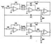
It has me stumped to. The 2nd opamps from the left seem to be integrators/low-pass filters. There is also feedforward through the capacitors from the input. Probably some clever combination of filtering and addition/subtraction of filtered signals and the original to get flat overall response?
Jan Didden
Peter,
It has me stumped to. The 2nd opamps from the left seem to be integrators/low-pass filters. There is also feedforward through the capacitors from the input. Probably some clever combination of filtering and addition/subtraction of filtered signals and the original to get flat overall response?
Jan Didden
If memory serves me well...
The circuits in question are implementations of biquad block diagrams. Using a very large resistor transforms the circuit block into a HP filter with a 2nd-order rolloff. On the other hand, bypassing the series resistor yields a linkwitz transform-like transfer function. A series resistor between these two extremes yields a "stepped" transfer function.
Looks like they were used for both equalization and attenuation.
.... an expert will come along soon")
The circuits in question are implementations of biquad block diagrams. Using a very large resistor transforms the circuit block into a HP filter with a 2nd-order rolloff. On the other hand, bypassing the series resistor yields a linkwitz transform-like transfer function. A series resistor between these two extremes yields a "stepped" transfer function.
Looks like they were used for both equalization and attenuation.
.... an expert will come along soon
f4ier said:
[snip]
.... an expert will come along soon
"When the mind is ready, a teacher appears"- Zen expression
Jan Didden
Hi f4ier
Your guess was quite good.
I performed a SPICE simulation on the one from the lopwpass branch and it's response looks like a lag filter with a notch or someting like a cauer filter without rolloff in the upper frequency range.
It's gain is 3.4 (i.e. somewhat larger than 10 dBs) at low frequencies, rising to 3.64 at 809 Hz (i.e. it has a hump). It then falls with a -3dB frequency (relative to LF gain) of 1.4kHz approx. It then continues to fall up to 2.4 kHz where there is a notch (approx 40 dB attenuation). It then returns to a gain of 1 which remains constant up to infinity (theoretically of course).
If one combines this with an ordinary 2nd order lowpass he will get a Cauer-like filter.
Regards
Charles
Jan, the original article by Bill Hardman appeared in the August 1999 issue of EW.
All others, I am not such a theoretical expert to give an all comprehensive summary of the schematic that I have posted. The original article is seven pages long. It makes very good reading from a technical aspect, but I wonder if copyright would debar me from posting all of the pages. Let me know on this aspect.
Hi f4ier and Phase_accurate(Charles) have got to the point. The first three opamps in each wing are used to produce a notch in the response. Yes, it is like a Cauer elliptic filter. Actually it is a Bainter filter, according to the author. The notches are produced by two complex zeros on the imaginary axis in the S-plane. They exhibit no group delay, nor varying phase shift with frequency; they rather have fixed phase shifts of 90 degrees. The pole locations of both the arms are the same and hence, they exhibit the same group delay.
The simulation results reported are close to accurate. All the zeros lie on the imaginary axis. The high-pass filter has two zeros
at the origin - 0Hz - and a complex zero at 807Hz. The low-pass filter has two zeros at infinity and a complex zero at 2775Hz.
The two arms do not have the same pass-band gain. The internal operting levels are higher than the output, requiring the outputs to be run 10db below the normal maximum.
This elliptic filter is followed by a second order LR Low/High pass filter respectively.
The two arms (High and Low pass) have no phase error throughout the crossover region. At the frequencies of the zeros, the phase difference is 180 degrees but at the same time it occurs in the filter stop band where there is more than 30db of attenuation. The slope of the filter lies between 6th and 8th order LR filter but have a low group delay. The outputs sum with less than 1db error.
The above comments are extracted from the original article which I would love for all those interested to read for themselves. Let me know about the copyright issue.
Subjective performance of the filter is the best that I have heard so far. As mentioned earlier, I am working on improving its transparency using discrete opamps.
Sam wrote:
With your 3-way setup, the treble driver output will pass through two filter networks: the LP filter of the bass driver, and the HP filter of the treble driver. Kind of a series arrangement of filter blocks. Is this an essential feature of Hardman's circuit? This is unlike a typical active XO, where the filter blocks are parallel, except for bandpass having HP/LP in series.
I want to adapt the circuit to 4-way or even 5-way, but if the filter blocks have to be cascaded in series, some drivers will have a LOT of circuit elements upstream. I think this is undesirable.
Please assure me that the Hardman circuit can be arranged in parallel filter blocks for multi-way applications.
Grant
I have configured the orginal two way into three way by duplicating the two way network at the output of the High/Low output. I preferred to tap off the Low output to the Amp, but pass the High output through another two way network to obtain Mid and High outputs.
With your 3-way setup, the treble driver output will pass through two filter networks: the LP filter of the bass driver, and the HP filter of the treble driver. Kind of a series arrangement of filter blocks. Is this an essential feature of Hardman's circuit? This is unlike a typical active XO, where the filter blocks are parallel, except for bandpass having HP/LP in series.
I want to adapt the circuit to 4-way or even 5-way, but if the filter blocks have to be cascaded in series, some drivers will have a LOT of circuit elements upstream. I think this is undesirable.
Please assure me that the Hardman circuit can be arranged in parallel filter blocks for multi-way applications.
Grant
mhelin, I would just scale the cap values by the factor of desired freq over 1500Hz, like Sam said in his first email in this thread.
I would still like to know any thoughts on my question yesterday about whether the filter blocks can be used in parallel for multi-way crossovers, or do they have to be in series like Sam arranged his 3-way?
Grant
I would still like to know any thoughts on my question yesterday about whether the filter blocks can be used in parallel for multi-way crossovers, or do they have to be in series like Sam arranged his 3-way?
Grant
I have been looking for documentation about the Bainter filter but Google didn't find much. A few days ago, I fall on this :
http://www.dogpile.com/
I used it with "Bainter", "notch" and "filter" as key words and, at last, found this long sought text :
http://oregonstate.edu/~kolstadj/Active Notch Filter (Bainter).pdf
I finished my stereo 1.5 kHz Hardman crossover a few weeks ago. I found this is really a winner I already knew the Hardman circuit and found it very interesting. Once I read Samuel Jayaraj's post, I decided to build a first mono PCB. The results were so good that I duplicate it for stereo. Damned good, now !
After some hesitation for a low frequency crossover at 150 Hz between the 18 dB/o Le Cleac'h and the 24 dB/o Linkwitz filters, and a few investigations about the amount of dB which must be rejected at loudspeaker resonance, I recently decided that my whole system will only use Hardman crossovers.
~~~~~~~~~ Forr
§§§
forr said:used it with "Bainter", "notch" and "filter" as key words and, at last, found this long sought text
Thanx for finding & posting that.
dave
Hi,
I think elliptic filters suited for audio are an interesting step for crossovers just as were the Linkwitz-Riley' 28 years ago..
Here Neville Thiele's patent :
http://www.pat2pdf.org/patents/pat6854005.pdf
I've simulated the Thiele's 4th order passive crossover using Tina.
Crossover at 1000 Hz, notches at 500 and 2000 Hz. The frequency response is very flat.
I then tried to obtain the same results using Bainter's notch,
crossover at 2000 Hz, and notches at 1000 Hz and 4000 Hz.
Despite experimenting with many various values, I could not get rid of response variations, at least 1 dB,
I feel a bit lost with what should be the Q of 2nd order filter section and how to set Bainter's circuit.
Can someone help ?
Since the old links don't work anymore I did the same: googl'it. I came across a very useful pdf. Look at pages 26, 45.
http://www.analog.com/library/analogDialogue/archives/39-05/Web_Ch5_final_PtB_F.pdf
Any good? My hard-disk said: gulp!, anyway...
http://www.analog.com/library/analogDialogue/archives/39-05/Web_Ch5_final_PtB_F.pdf
Any good? My hard-disk said: gulp!, anyway...
- Home
- Loudspeakers
- Multi-Way
- The Best Active Crossover - Here!