Hi All,
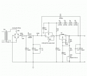
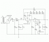
If any of you have looked at the "using back to back LT1085s" thread this is the same reg but the requirments have changed and I want to make sure that I have it right before I have the boards made. I now only need 15 volts. I should be dropping about 11 volts across the pre reg and about 8 volts across the output reg. I know that the output reg is adjusted properly for a 15 volt output but I'm not positive about the pre reg. Can anyone spare a few minutes to help me?
If any of you have looked at the "using back to back LT1085s" thread this is the same reg but the requirments have changed and I want to make sure that I have it right before I have the boards made. I now only need 15 volts. I should be dropping about 11 volts across the pre reg and about 8 volts across the output reg. I know that the output reg is adjusted properly for a 15 volt output but I'm not positive about the pre reg. Can anyone spare a few minutes to help me?
Attachments
The schematics looks OK at the first glance but what is the purpose of the circuit?
If you want 15 volts out, have lots of "volts" to burn away and constant load, why don't you use a R+C filter and burn away the power in the R's. Check my MC amp power supply. If you have lots of R's I think the surpression of interference will be good and it's a simple solution.
My regulator has first R in the rectifying bridge then 470 µF, then a huge R-C filter. The resulting unregulated voltage is very clean. If your load is rather constant skip the inductor (unless you think it's cool). Better to burn volts in a resistor instead.
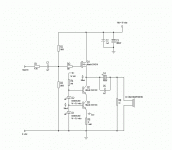
Hi Peranders. Well the circuit is a tracking regulator as I'm sure is obvious to you. Why use it? Well I guess just for really good regulation for the circuit below. Is the load constant? I don't think so but I'm not going to give you a definite no because I'm not sure. The current load on the PSU could be anywhere from 233mA at idle to 1 amp on loud passages. The circuit below is a modified Szekeras headphone driver. The reg I'm sure is probably a little overkill but not really that expensive or hard to build so what the hell. Thanks for replying.
Attachments
The schematics looks OK at the first glance but what is the purpose of the circuit?
If you don't know the pupose of the circuit and what he is trying to achieve how can you tell if the circuit is alright? He wants to see if this circuit is optimal, not go design a new one. I don't see that your advice is helpful at all. An LC filter is better than an RC for Power supply rejection. If you are not going to be helpful,, why not remained silent
Art
If you don't know the pupose of the circuit and what he is trying to achieve how can you tell if the circuit is alright? He wants to see if this circuit is optimal, not go design a new one. I don't see that your advice is helpful at all. An LC filter is better than an RC for Power supply rejection. If you are not going to be helpful,, why not remained silent

Art
Suggestions to consider:
1) Increase the 5.6 K Ohm resistor and (possibly) decrease the trimpot -- if you want 15 Vfigure out what the total of the two should be and make the pot perhaps only 10% of the total. That way you get a finer control. Or increase the 5.6 K and use a parallel resistor alongside the 2K trimpot to effectively decrease the trimpot so that if the wiper opens you don't totally lose it. Of course, the circuit doesn't need or particularly benefit from 15.00000 V so maybe you can just use a fixed resistor here with no trim. [ I remember watching Julia Child say "put in EXACTLY 1 tablespoon of salt" while throwing in a careless handful of salt to the pot ]
2) Take the suggetion above of using a power resistor to drop the first 11V, Use 1 LT1085 for the 15V rail, and use the other one for the 10 V gate bias; feed it to the gate through a 100 K resistor instead of the 100K and 200K voltage divider. You could also use the second one to feed the Q2/Q3 current source after appropriately adjusting the value of R4.
3) Like 2, drop 11 V with a resistor, use 1 LT1085 for the 15V rail and the other connected as a 233 mA current source [LT almost surely has an app note on this] in place of the Q2/Q3 current source.
I don't quite get the benefit of cascoding the Q3 current source with Q2; the output conductance of the current source shouldn't really matter because you have a 1K resistor and the load effectively shunting it anyway, and the cascode eats into the available voltage headroom before clipping.
Suggestion number 1 will make the circuit easier to adjust and perhaps more reliable.
Suggestion number 2 would probably have the most beneficial effect on the sound because it would allow a stabilize the bias point of the mosfet with a regulator that has no variation in its current demand.
Number 3 is for experimenting -- who knows if the LT1085 as a current source sounds as good / worse / better than the discrete circuit.
Hello,
If my memory serves me correct, Benny Jorgensen did something similar in his headphone amp.
 Link removed
He says something about making CS faster and more precise. I don't see it though by cancelling capacitance of the lower transistor. ... I have no idea what it means.
I have seen Rod Elliot use a darlington pair in his CCS which is good idea when you need large current.
Tomo
If my memory serves me correct, Benny Jorgensen did something similar in his headphone amp.
 Link removed
He says something about making CS faster and more precise. I don't see it though by cancelling capacitance of the lower transistor. ... I have no idea what it means.
I have seen Rod Elliot use a darlington pair in his CCS which is good idea when you need large current.
Tomo
Last edited by a moderator:
- Status
- This old topic is closed. If you want to reopen this topic, contact a moderator using the "Report Post" button.
- Home
- Amplifiers
- Solid State
- Need help with tracking regulator adjustment. Please.


