Hi there,
Quite many related posts here somewhere, but they are all very long already, so I'd like to create a new thread.
Back in '97 when I read about the Euridice pre amp on the <Sound Practices>, I thought "this is it!".
All these years I've been thinking of it. And my own thoughts about "pre amp" have also been evolving continuously. (especially the concept of digital xover made a big impact)
My own "designs" around original Euridice had evolved to several versions including differential pair, with regulated supply, or even shunt regulator with pentode current source & the likes. I've drawn 5~6 versions of the schematics of such line stage & power supplies. And they looked more & more complicated. In the end, it seemed that I just wanted to use as many tubes as I have on hand, instead of seeking the best & proper solution.
My previous pre amp was SOZ, sounded OK. A little bit vague in the high & soft on bass but overall open & warm-balanced. And I had an OPAmp-based 2nd order LP filter for the bass amps.
Now I want to combine the pre amp & the active xover into one chassis to simplify my system. So, actually I need 4 active channels in this unit. With this construction, no matter I use it analogically xover now or digitally xover in the future, it's ready as a convenient platform.
After thoroughly readings & thinking, I dropped those complications & made it as simple as can be. Back to basic & decent executions are all I need.
So here it is:
1) LL7902 wired as 2:1 step down input transformer with a 10k load (stepped volume control). I'd like to make a relatively easy load to the upstream equipment. I've tried "DAC chip-direct" with this transformer and got a very good sound. I'll probably do it again. Now the transformers are much further from the chip, so a step down would make it an easier load.
2) The wiping arms of the stepped VR are connected to 2 loads: 1 for passive 1st order HPF & the other to a 2nd order active LPF, both gain stages are mostly original "Euridice".
3) Output transformers are LL1660 (18mA), wired as 4.5:1 (or, 5k:250R approx. )
4) Powered by 2* 6X5GT with 2* 1N4007 as one & a half bridge, fed into 2* 15H/220uF LC, then splitted into 4* 2k/1000uF RC for each tube.
Layout:
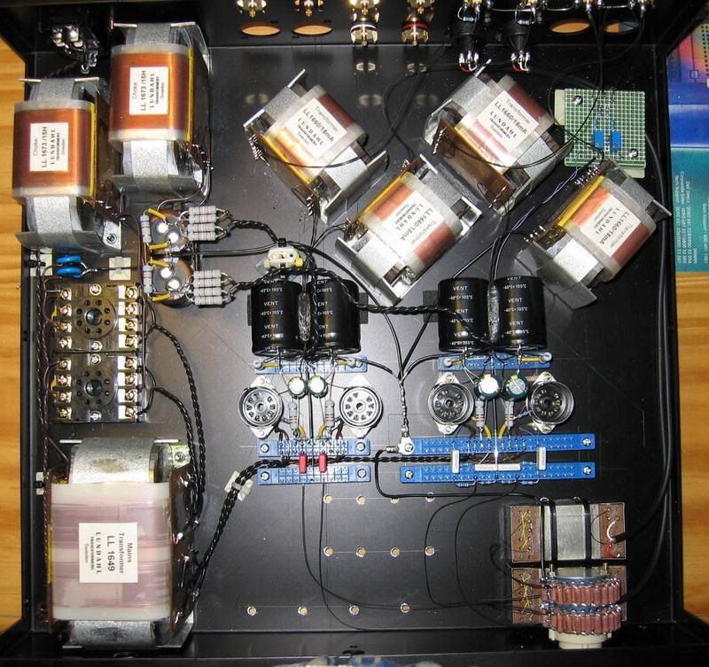
Notice the left, see the "relay socket" ? It's because the limited height, I can not afford to elevate the normal 8pin socket in this cabinet. And I found it a breeze to connect around such socket. Easy & neat!
The output transformers are arranged so for avoiding/reducing magnetic coupling to each other & the power chokes. But I confess, I've done this by "pure guess", instead of real experiments. (There are A LOT OF holes to drill on the chassis, I don't have time to build-test-rebuild... ) I've thought about separating the power portion to another cabinet, but that complicated things in some ways.
There's a massive terrible hum in the first test. Tens of mV of hum! Then I made a virtual CT of the heater winding by 2* 47R & connected the center to ground. That cured the hum mostly but not entirely. ( I'm confused, aren't those heaters insulated from cathodes? Why can't I just let them float? )
In the first 2~3 hours, it sounded awful, really. Strained in the high & bass was non-existent. After that, it loosened up nicely with good extension on both ends. It's sounding good indeed, with crisp trancient, clean & lively performance, but the "upgrading effect" was not so astonishing as Oris horn in my system. Listening carefully, it's surely an upgrade to my previous SOZ in every aspects, but not so hugely as expectation. (my SOZ was biased at 40mA, I like the sound of "big current" )
Concerns & possible tunings:
1) Hum! It's still there, although barely audible on the listening position, it'd of course be better totally gone. I got approx. 0.5V ripple on the B+, but there's no space for more LC or RC. And the heaters are AC powered.
a) Does Ultra-path work on such circuit? If the hum is partially caused by magnetic coupling, does Ultra-path help?
b) Is DC heater necessary or any help?
2) I got 155V B+ after LCRC, 5V shied of the original 160V. With the same 120R cathode resistor, I got only -1.7V bias, which is only 14mA. In the Raytheon specs, it recommand 150V B+ with 60R cathode resistor to get -1.5V bias & 25mA, so I'll probably try this. This tube seems prefer high current to high voltage. So I'll try maintaining the B+ with more current.
3) LL1660 output transformer has 100H in the primary winding. With pretty low plate resistance of CK5842, ideally I can get very very low frenquency out of it. To let them sing all the way down, I use huge cathode bypass caps here - 1000uF in mid-high channels & 2200uF in lows. I'm not sure, before realizing the lowest 1.3Hz or 0.6Hz, there might be other evils coming up. Or, once I try smaller cathode resistor, this "issue" would be mostly gone?
4) 2:1 step down on the input seemed unecessary. And it made the total gain too small, I'll probably rewire them into simply 1:1 isolation. Working around those tiny pins is really painful though...
5) I got several 6C45 lying around, maybe worth a try in this circuit. I've had a simple test on microphonia by tappin on the glass. The CK5842 has a relatively firm & short "tung", and the 6C45 in my 300B power amp has a crisp & very long "ding-ring-ring-ring- ing -ing -ing -ing -ing ....... ". ( Except for tubes themselves, maybe it's also because the 6C45 is working under plate choke / direct coupling with most of its natural amplification, and the 5842 is working with a largely stepped down output trans. I'll do more experiments on these tubes.... )
So, thanks for reading such a long post. It's probably an "old" topic.
Any corrections, suggestions, & thoughts are more than welcome.
Quite many related posts here somewhere, but they are all very long already, so I'd like to create a new thread.
Back in '97 when I read about the Euridice pre amp on the <Sound Practices>, I thought "this is it!".
All these years I've been thinking of it. And my own thoughts about "pre amp" have also been evolving continuously. (especially the concept of digital xover made a big impact)
My own "designs" around original Euridice had evolved to several versions including differential pair, with regulated supply, or even shunt regulator with pentode current source & the likes. I've drawn 5~6 versions of the schematics of such line stage & power supplies. And they looked more & more complicated.
In the end, it seemed that I just wanted to use as many tubes as I have on hand, instead of seeking the best & proper solution.My previous pre amp was SOZ, sounded OK. A little bit vague in the high & soft on bass but overall open & warm-balanced. And I had an OPAmp-based 2nd order LP filter for the bass amps.
Now I want to combine the pre amp & the active xover into one chassis to simplify my system. So, actually I need 4 active channels in this unit. With this construction, no matter I use it analogically xover now or digitally xover in the future, it's ready as a convenient platform.
After thoroughly readings & thinking, I dropped those complications & made it as simple as can be. Back to basic & decent executions are all I need.
So here it is:
1) LL7902 wired as 2:1 step down input transformer with a 10k load (stepped volume control). I'd like to make a relatively easy load to the upstream equipment. I've tried "DAC chip-direct" with this transformer and got a very good sound. I'll probably do it again. Now the transformers are much further from the chip, so a step down would make it an easier load.
2) The wiping arms of the stepped VR are connected to 2 loads: 1 for passive 1st order HPF & the other to a 2nd order active LPF, both gain stages are mostly original "Euridice".
3) Output transformers are LL1660 (18mA), wired as 4.5:1 (or, 5k:250R approx. )
4) Powered by 2* 6X5GT with 2* 1N4007 as one & a half bridge, fed into 2* 15H/220uF LC, then splitted into 4* 2k/1000uF RC for each tube.
Layout:
Notice the left, see the "relay socket" ? It's because the limited height, I can not afford to elevate the normal 8pin socket in this cabinet. And I found it a breeze to connect around such socket. Easy & neat!
The output transformers are arranged so for avoiding/reducing magnetic coupling to each other & the power chokes. But I confess, I've done this by "pure guess", instead of real experiments. (There are A LOT OF holes to drill on the chassis, I don't have time to build-test-rebuild... ) I've thought about separating the power portion to another cabinet, but that complicated things in some ways.
There's a massive terrible hum in the first test. Tens of mV of hum! Then I made a virtual CT of the heater winding by 2* 47R & connected the center to ground. That cured the hum mostly but not entirely. ( I'm confused, aren't those heaters insulated from cathodes? Why can't I just let them float? )
In the first 2~3 hours, it sounded awful, really. Strained in the high & bass was non-existent. After that, it loosened up nicely with good extension on both ends. It's sounding good indeed, with crisp trancient, clean & lively performance, but the "upgrading effect" was not so astonishing as Oris horn in my system. Listening carefully, it's surely an upgrade to my previous SOZ in every aspects, but not so hugely as expectation. (my SOZ was biased at 40mA, I like the sound of "big current" )
Concerns & possible tunings:
1) Hum! It's still there, although barely audible on the listening position, it'd of course be better totally gone. I got approx. 0.5V ripple on the B+, but there's no space for more LC or RC. And the heaters are AC powered.
a) Does Ultra-path work on such circuit? If the hum is partially caused by magnetic coupling, does Ultra-path help?
b) Is DC heater necessary or any help?
2) I got 155V B+ after LCRC, 5V shied of the original 160V. With the same 120R cathode resistor, I got only -1.7V bias, which is only 14mA. In the Raytheon specs, it recommand 150V B+ with 60R cathode resistor to get -1.5V bias & 25mA, so I'll probably try this. This tube seems prefer high current to high voltage. So I'll try maintaining the B+ with more current.
3) LL1660 output transformer has 100H in the primary winding. With pretty low plate resistance of CK5842, ideally I can get very very low frenquency out of it. To let them sing all the way down, I use huge cathode bypass caps here - 1000uF in mid-high channels & 2200uF in lows. I'm not sure, before realizing the lowest 1.3Hz or 0.6Hz, there might be other evils coming up. Or, once I try smaller cathode resistor, this "issue" would be mostly gone?
4) 2:1 step down on the input seemed unecessary. And it made the total gain too small, I'll probably rewire them into simply 1:1 isolation. Working around those tiny pins is really painful though...
5) I got several 6C45 lying around, maybe worth a try in this circuit. I've had a simple test on microphonia by tappin on the glass. The CK5842 has a relatively firm & short "tung", and the 6C45 in my 300B power amp has a crisp & very long "ding-ring-ring-ring- ing -ing -ing -ing -ing ....... ". ( Except for tubes themselves, maybe it's also because the 6C45 is working under plate choke / direct coupling with most of its natural amplification, and the 5842 is working with a largely stepped down output trans. I'll do more experiments on these tubes.... )
So, thanks for reading such a long post. It's probably an "old" topic.
Any corrections, suggestions, & thoughts are more than welcome.
Last edited:
Konnichiwa,
Heater and cathode form a parasitic rectifier diode which injects rectified AC into the cathode. You can avoid problems from this by reverse-biasing this diode to more than the peak voltage of the heater, so try returning your virtual center-tap to around +20V instead of ground, but make sure there is low impedance to ground.
Sayonara
CLS said:There's a massive terrible hum in the first test. Tens of mV of hum! Then I made a virtual CT of the heater winding by 2* 47R & connected the center to ground. That cured the hum mostly but not entirely. ( I'm confused, aren't those heaters insulated from cathodes? Why can't I just let them float? )
Heater and cathode form a parasitic rectifier diode which injects rectified AC into the cathode. You can avoid problems from this by reverse-biasing this diode to more than the peak voltage of the heater, so try returning your virtual center-tap to around +20V instead of ground, but make sure there is low impedance to ground.
Sayonara
in euridice type of preamp,I prefere CCS for heaters,also elevated to at least 50 volts potential via divider;that divider must burn at least 2 mA to achieve good results and must be decoupled via minimum 10 micro.
try also to use smallest cap you can for cathode decoupling or ,even better, use NiCd instead of cathode resistor.
that's my opinion
look at http://choky.on.neobee.net for my WOT preamp
try also to use smallest cap you can for cathode decoupling or ,even better, use NiCd instead of cathode resistor.
that's my opinion
look at http://choky.on.neobee.net for my WOT preamp
Thanks for all your reply
The relay socket is marked Omron, bought just from the local electronic part store. It's well-made, and cramps the tube tightly.
All the Lundahls, hehe, I bought them years ago before I got married And I got some other which are enough for building a pair of mono block power amps. (maybe another or two more pairs of IT will be needed )
About the power choke concerns, I remeber in some books somewhere, the magnetic leak would be mostly in north-south direction (on the viewpoint of the picture above). I'm not sure how it'd actually be. For precaution (or my obsession), I wired the 2 chokes in oppiste direction. Also, I don't know if this helps or does the opposite. Changing the wiring is easy, I can do some experiment about that in the future.
Observed from the horn mouths, it seemed more hum on the left channel than the right. And that's the output transformer which is nearest to the choke. The difference is not very much though.
About the cathode bypass caps, is there any catch on their value? I've read that its low cut frequency should be at least 1 or 2 octaves below the rest of circuit can handle. I suppose it's for the phase stability?
I think the bottle neck of this portion should be the output transformer. It's a nominal 100H in the primary winding of LL1660, and a nominal 11Hz lowest frequency on 3k source impedance. Now it works with 5842 which Rp is about 1.6~1.7k, so I expect 6~7Hz on the bottom. If that's the case, 1 octave below is 3Hz, 2 is 1.5Hz. With 120R cathode resistor, the caps would be 470 & 1000 respectively (common values).
In the "original" design, this cap is 220, which represents 1 octave higher. However, its output transformer has only 15H in the primary winding.
hmm......
Anyway, I'll try more RC combinations on this.
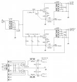
For those insterested in the schematics, please see the attachment below. This is the current version, will surely be changed in the near future.
In the LPF portion, I took 2 sets of RC in the same value & use the feedback to tune the filter Q. This is derived from the books and was working good on my previous OP-based xover. However in this circuit, tuning the VR got little effect. I'm confused on this portion, will try more in the future.
Again, any thoughts or suggetions are appreciated.
I'll also keep updating for any changes & results.
The relay socket is marked Omron, bought just from the local electronic part store. It's well-made, and cramps the tube tightly.
All the Lundahls, hehe, I bought them years ago before I got married
And I got some other which are enough for building a pair of mono block power amps. (maybe another or two more pairs of IT will be needed )About the power choke concerns, I remeber in some books somewhere, the magnetic leak would be mostly in north-south direction (on the viewpoint of the picture above). I'm not sure how it'd actually be. For precaution (or my obsession), I wired the 2 chokes in oppiste direction. Also, I don't know if this helps or does the opposite. Changing the wiring is easy, I can do some experiment about that in the future.
Observed from the horn mouths, it seemed more hum on the left channel than the right. And that's the output transformer which is nearest to the choke. The difference is not very much though.
About the cathode bypass caps, is there any catch on their value? I've read that its low cut frequency should be at least 1 or 2 octaves below the rest of circuit can handle. I suppose it's for the phase stability?
I think the bottle neck of this portion should be the output transformer. It's a nominal 100H in the primary winding of LL1660, and a nominal 11Hz lowest frequency on 3k source impedance. Now it works with 5842 which Rp is about 1.6~1.7k, so I expect 6~7Hz on the bottom. If that's the case, 1 octave below is 3Hz, 2 is 1.5Hz. With 120R cathode resistor, the caps would be 470 & 1000 respectively (common values).
In the "original" design, this cap is 220, which represents 1 octave higher. However, its output transformer has only 15H in the primary winding.
hmm......
Anyway, I'll try more RC combinations on this.
For those insterested in the schematics, please see the attachment below. This is the current version, will surely be changed in the near future.
In the LPF portion, I took 2 sets of RC in the same value & use the feedback to tune the filter Q. This is derived from the books and was working good on my previous OP-based xover. However in this circuit, tuning the VR got little effect. I'm confused on this portion, will try more in the future.
Again, any thoughts or suggetions are appreciated.
I'll also keep updating for any changes & results.
Attachments
I think where you find an octal 8pin general purpose relay, you also find this socket. Omron PF083A is used in this pre amp. I also saw similar stuff in Digikey's catalog.
----------------------
Last night I managed to have the following mods done:
1. Elevating the heater supplies by approx. 20V
2. Reducing the cathode resistor to 49R9
3. Reducing the RC filter's R from 2K to 330R
4. Adding Ultra-path caps
5. Replacing the grid stopper resistors to ferrite beads
6. Rewiring the input transformer to 1:1
7. Adding 2* 0.1R in each heater supply circuits.
2&3 above brought the operation point to 140~V on the anode, -1.25V bias & 25mA. The load line is slightly higher than the "original" 160V/20mA, & in the point of somewhat lower V & higher I. On the curves, it looked good.
It was 1am when I finished them, so no energy left to do a listening test.
With larger current draw, I found the ripples on power rails also enlarged a little. By DMM, I saw the output hum/noise was still 1.1~1.2mV as before. I know, this is bad
I don't fully understand how the Ultra-path works. According to TubeCAD Journal, the cap value is proportional to the amplication realized in the circuit & the cathode cap size. By this, I chose 33u as a trial, assuming I got 30 some of gain.
What would happen if this cap is over-sized? Over-compensation?
Anyway, I can't wait to have a listening to the newly mods.
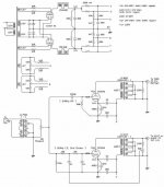
Attachments
Konnichiwa,
I think there is a real problem in your HT supply. The 330R/1,000uF RC filters should suppress the around 0.7V ripple after first Choke Input filter by 46db, or make it around 3.5mV. Your notes sem to suggest that this is not the case. I would however expect nearly 1mV hum in the circuit as is.
You might want to replace the 330R Resistors with some nice chokes, they don't need to be too huge.
With the WE Connection in place (you need 24uF for maximum PSRR) BTW you should have an extra at least 20db PSRR so your noise should drop to around 0.1mV with 22uF from +B to cathode IF the source is the +B line.
In order to check if the hum is from the +B line or from other sources replace the Valves with power resistors drawing about the same current as the valves, then measure ripple again.
You need to use Mu at the operating point (41 IIRC for the 5842) not stage gain. P-Spice is a good tool to test this out. I find that tuning the WE Capacitor for best (lowest) noise gets past 30db extra noise reduction in the real world.
Sayonara
CLS said:With larger current draw, I found the ripples on power rails also enlarged a little. By DMM, I saw the output hum/noise was still 1.1~1.2mV as before. I know, this is bad
I think there is a real problem in your HT supply. The 330R/1,000uF RC filters should suppress the around 0.7V ripple after first Choke Input filter by 46db, or make it around 3.5mV. Your notes sem to suggest that this is not the case. I would however expect nearly 1mV hum in the circuit as is.
You might want to replace the 330R Resistors with some nice chokes, they don't need to be too huge.
With the WE Connection in place (you need 24uF for maximum PSRR) BTW you should have an extra at least 20db PSRR so your noise should drop to around 0.1mV with 22uF from +B to cathode IF the source is the +B line.
In order to check if the hum is from the +B line or from other sources replace the Valves with power resistors drawing about the same current as the valves, then measure ripple again.
CLS said:I don't fully understand how the Ultra-path works. According to TubeCAD Journal, the cap value is proportional to the amplication realized in the circuit & the cathode cap size. By this, I chose 33u as a trial, assuming I got 30 some of gain.
You need to use Mu at the operating point (41 IIRC for the 5842) not stage gain. P-Spice is a good tool to test this out. I find that tuning the WE Capacitor for best (lowest) noise gets past 30db extra noise reduction in the real world.
Sayonara
KYW,
Thanks a lot for your informative reply.
Excuse me but what does "WE" stand for here? "THE" WE, or something else? I supposed it's the same as so-called ultra-path?
The two caps 33 & 1000 in series act as a voltage divider. Here the AC voltage divided by them should be 33/1033 at the cathode, which is 0.6* 33/1033=0.02VAC (20mVAC) !!
If I took the DC volage proportion to estimate the AC component, then it's 4.3mV.
But last night I measured the cathode voltage & found there's only 1.4mV AC on it. It's odd. I cannot pull them together.
Am I missing something here?
Another concern on the cap value is the RC filtering. If I took this 33u cap & the Rk of 49R9, I got a 1st order 96Hz (-3dB) HPF. If the cap was reduced to 22u, then the frenquency would rise to 145Hz. Facing the strongest 120Hz AC noise here, would this be a pitfall? (In this case the attenuation on 120Hz is only a few dB, what if in other smaller RC combinations with much higher low cut frequency?)
As for the tubes, I think they're probably OK. There are 4 of them & they perform similarly. After 2~3 hours of operation, their bias currents are 22mA, 24mA (*2), 25mA respectively. On the "sensitive" little tubes like these, such differences should be OK, I supposed? And they also sounded OK.
Yes, despite the dirty power rails, this amp sounds good, better then before. With larger current flow, the tubes operate on the straighter part of the curves. It sounds crisper, faster, more energetic with sharp & clean attacks. Also with very audible differences in high & low's extension.
I noticed several loud pops came on when the light of the next room was switched on/off. This never happened before. I'm not sure if this was caused by the much-questionable power supply or the re-wired input transformer.
About the input transformer, I'm also worrying. I got louder noise when the VR was turned fully clockwise. It changed obvious in the last several steps. Also, this never happened when I wired it as 2:1 stepdown.
Back to the power supply's foundation, I might try to reconfig them to LCLCRC or give up the regulation & make it CLCLCRC..... In the end, I'll keep them in the same chassis as possible.
It seems there's still much work to do... sigh...
Konnichiwa,
What is now called Ultrapath was invented by WE (and in some cases parallel by TFK & Siemens) in the 1920's & 30's. This includes the "Ultrapath" Capacitor and the use of a Transformer as Volume control.
Once the circuit operates things become. stange. Before you can kill the hum you need to know where it's hailing from....
But this capacitors current loop does not include the Cathode R. It is the coupling capacitor for the output transformer!!! (yes, even in series feed there is ALLWAYS a coupling capacitor).
Sayonara
CLS said:Excuse me but what does "WE" stand for here? "THE" WE, or something else? I supposed it's the same as so-called ultra-path?
What is now called Ultrapath was invented by WE (and in some cases parallel by TFK & Siemens) in the 1920's & 30's. This includes the "Ultrapath" Capacitor and the use of a Transformer as Volume control.
CLS said:But last night I measured the cathode voltage & found there's only 1.4mV AC on it. It's odd. I cannot pull them together.
Am I missing something here?
Once the circuit operates things become. stange. Before you can kill the hum you need to know where it's hailing from....
CLS said:Another concern on the cap value is the RC filtering. If I took this 33u cap & the Rk of 49R9, I got a 1st order 96Hz (-3dB) HPF.
But this capacitors current loop does not include the Cathode R. It is the coupling capacitor for the output transformer!!! (yes, even in series feed there is ALLWAYS a coupling capacitor).
Sayonara
I reconfigured the chokes added more filter onto the power supply. Now it's:
Parelleled 6X5GT fed into a 2u motor start cap, then 15H ->100u*2 -> 15H -> 180u*2 -> splitted 2* 120R/200u RC -> splitted 4* 1k/1000u RC
Funny enough, now the ripples on the series 2 LC are larger than the independ LC before, which are 0.79V & 0.76V. Then the following 2 stages of RC show 0.73 & 0.6V of ripples. (The final voltage on the tubes is lowered by several volts, though, thus slightly shifting down the operation point...)
Which means, the power is not any cleaner then before
However, the outputs are indeed a little bit cleaner, 1.1mV on the DMM. And much cleaner on the listening test. Now the slight hum from the speakers is almost all from the power stage. Turning the VR of power amp shows no change (enlargement) to the hum.
I now suspect the DMM is not trustable.....
And it does sound cleaner, smoother, more fluid-like, & the dynamics is well maintained, which is of course better (to me at least).
The last 3~4 steps on the VR still show some buzz on the output, I've not rewired the input transformer yet... I'm not worry about it though, those positions are almost never used.
BTW, the WE (ultrapath) connections are now cancelled. Although it's not likely, maybe something was wrong in my previous installation.
The Latest Updates
The LPF section in the previous version didn't work properly. Using RTA & a very close mic position, I saw a very shallow attenuation curve. Full output was only seen on 50~40Hz region & below. Above that, the output dropped. At the expected -3dB point, 160Hz, it already dropped more than 10dB. Above that, the slope seemed not any steeper
Originally I put the feed back point on the OPT's secendary & used a trim pot to set the gain & Q. But tuning the pots didn't alter the response curve at all. In such situation, the low output on upper bass region made the sound a little bit ¡§weak¡¨. Although I can¡§fix¡¨this by the upstream DEQ, after all it¡¦s cheating.
So eventually I reconnected the feedback point to the cathode & eliminated the cathode bypass caps. Also, the caps' values in the RC filters were changed for obtaining a proper Q.
Meantime, evaluating the power amps¡¦gains & the speakers¡¦ sensitivities, I decided to change the OPT configuration of this LPF section to get more gain. I rewired them to 2.25:1, thus approx. 5k:1k.
By doing all these, the bass response is much richer & more powerful. It somewhat alter the previous sharp & fast characters to a warmer & richer feels.
---------------
As to the noises, however, it¡¦s still very frustrating. I got some irregular & severe pops & bangs. After some experiments, I finally traced down to the cause¡Xone of the cathode circuit, it made the operation unstable.
The hum is now low, but I get a more obvious buzzZZZZ I¡¦ve tried twisting the input wires with ground wire after volume control. It helped a little but not much.
I highly suspect the interferences of chokes & OPT now, because the closest one is the noisiest channel.
Now the question is, wrapping the chokes & OPT with copper foil tape does any good to this? How can I do this practically?
Or should I build some ¡§walls¡¨ in the cabinet for isolation? I only got some 1.2mm sheet aluminum, would this help?
The LPF section in the previous version didn't work properly. Using RTA & a very close mic position, I saw a very shallow attenuation curve. Full output was only seen on 50~40Hz region & below. Above that, the output dropped. At the expected -3dB point, 160Hz, it already dropped more than 10dB. Above that, the slope seemed not any steeper
Originally I put the feed back point on the OPT's secendary & used a trim pot to set the gain & Q. But tuning the pots didn't alter the response curve at all. In such situation, the low output on upper bass region made the sound a little bit ¡§weak¡¨. Although I can¡§fix¡¨this by the upstream DEQ, after all it¡¦s cheating.
So eventually I reconnected the feedback point to the cathode & eliminated the cathode bypass caps. Also, the caps' values in the RC filters were changed for obtaining a proper Q.
Meantime, evaluating the power amps¡¦gains & the speakers¡¦ sensitivities, I decided to change the OPT configuration of this LPF section to get more gain. I rewired them to 2.25:1, thus approx. 5k:1k.
By doing all these, the bass response is much richer & more powerful. It somewhat alter the previous sharp & fast characters to a warmer & richer feels.
---------------
As to the noises, however, it¡¦s still very frustrating. I got some irregular & severe pops & bangs. After some experiments, I finally traced down to the cause¡Xone of the cathode circuit, it made the operation unstable.
The hum is now low, but I get a more obvious buzzZZZZ
I¡¦ve tried twisting the input wires with ground wire after volume control. It helped a little but not much. I highly suspect the interferences of chokes & OPT now, because the closest one is the noisiest channel.
Now the question is, wrapping the chokes & OPT with copper foil tape does any good to this? How can I do this practically?
Or should I build some ¡§walls¡¨ in the cabinet for isolation? I only got some 1.2mm sheet aluminum, would this help?
Now Solo, but it's OK
Finally, I found a major fault on the previous installment- a ground loop
This is a 2in-4out unit, so inevitability the "signal ground" splits at the input.
And I built it in one chassis & all 4 channels share the same power source, so the "power ground" splits here.
So, in between, a big circle
I rearranged the ground routing several times, finally found a good single point to ground to avoid most of the noise -- near the "power ground" point. The signal ground is broken on the LPF section, so the loop is also broken.
Meantime, I also tried reconnecting the chokes into a common mode operation, making HT & return sides in series. I've read an article which highly recommends this connection, so I gave it a try.
The input transformer was re-configured, too. Revewing the datasheet, I finally realise that the ultra high level is not needed here. So I rewired all the coils in parallel to get a very low DCR thus low copper loss. Doing this way, I lost the CT, so I just float the GND wire of the balance input.
Now this pre amp sounds even better The buzz is almost completely gone. Turning the volume controls of the downstream power amps from min to max shows NO change on the noise of the speaker output. (I stuffed my head into the horn when testing).
The most noticeable improvement on sound quality is the high. May I say it's so delicacy & airy At quiet night, listening in low level is a real treat. Effortless details are floating in the air and filling the room. I think the input transformer is the key.
However, thing's never perfect. Although most of the time the output is clean & quiet, at the last few steps of the volume control, some buzz grows & finally becomes offensive at max.
I guess connecting the GND of balance input to the secondary's ground might resolve this full output buzz, but have not tried it yet. However, this somewhat "wastes" the isolation it provides.
On the circuit diagram of the magnificent Marantz T-1, I see the balance input ground is connected to the common ground via a little choke (or just a ferrule?). I guess this might filter out some high frequency rubbish in the ground route, just like the trick on connecting "digital ground" & "analog ground" on the DAC PC board?
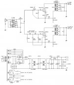
Attached is the latest circuit diagram, in case some of you are interested.
Finally, I found a major fault on the previous installment- a ground loop
This is a 2in-4out unit, so inevitability the "signal ground" splits at the input.
And I built it in one chassis & all 4 channels share the same power source, so the "power ground" splits here.
So, in between, a big circle
I rearranged the ground routing several times, finally found a good single point to ground to avoid most of the noise -- near the "power ground" point. The signal ground is broken on the LPF section, so the loop is also broken.
Meantime, I also tried reconnecting the chokes into a common mode operation, making HT & return sides in series. I've read an article which highly recommends this connection, so I gave it a try.
The input transformer was re-configured, too. Revewing the datasheet, I finally realise that the ultra high level is not needed here. So I rewired all the coils in parallel to get a very low DCR thus low copper loss. Doing this way, I lost the CT, so I just float the GND wire of the balance input.
Now this pre amp sounds even better
The buzz is almost completely gone. Turning the volume controls of the downstream power amps from min to max shows NO change on the noise of the speaker output. (I stuffed my head into the horn when testing). The most noticeable improvement on sound quality is the high. May I say it's so delicacy & airy
At quiet night, listening in low level is a real treat. Effortless details are floating in the air and filling the room. I think the input transformer is the key.However, thing's never perfect. Although most of the time the output is clean & quiet, at the last few steps of the volume control, some buzz grows & finally becomes offensive at max.
I guess connecting the GND of balance input to the secondary's ground might resolve this full output buzz, but have not tried it yet. However, this somewhat "wastes" the isolation it provides.
On the circuit diagram of the magnificent Marantz T-1, I see the balance input ground is connected to the common ground via a little choke (or just a ferrule?). I guess this might filter out some high frequency rubbish in the ground route, just like the trick on connecting "digital ground" & "analog ground" on the DAC PC board?
Attached is the latest circuit diagram, in case some of you are interested.
Attachments
I know this principle & done it on other stuff I made, but I got a dilemma here.
The "power ground" is at the end (or leans to the end of signal paths), and it's an unbreakable single point.
If I ground the the start, then in between this point & the "power ground", it'd be a big circle.
Or, later I'll draw some diagram to show the real layout....
The "power ground" is at the end (or leans to the end of signal paths), and it's an unbreakable single point.
If I ground the the start, then in between this point & the "power ground", it'd be a big circle.
Or, later I'll draw some diagram to show the real layout....
The overall layout is shown in the 1st post's picture.
Here is the wire routing:
On the signal lines lead to HP section, I made two thin wires twisted around them as a "shield" and they are connected on the circuit side & open on the start.
The signal lines lead to LP section are left un-shielded.
On this layout you may see, if I ground the input, then the power grounds of the 2 sections & the input would form a big closed triangle
BTW, the photo on the 1st post is out of date in the power supply portion, here is the latest version:
Here is the wire routing:
An externally hosted image should be here but it was not working when we last tested it.
On the signal lines lead to HP section, I made two thin wires twisted around them as a "shield" and they are connected on the circuit side & open on the start.
The signal lines lead to LP section are left un-shielded.
On this layout you may see, if I ground the input, then the power grounds of the 2 sections & the input would form a big closed triangle
BTW, the photo on the 1st post is out of date in the power supply portion, here is the latest version:
An externally hosted image should be here but it was not working when we last tested it.
LL1630
I built about the same schematic with Luhndal LL1630 transformer as output.
PSU is CLCLC. Simple but very very good sound. Can be used as pre-amp or as headphone amp.
Could be a better choice than euridici
simpler is sometimes better or at least less chance on problems and it is cheaper
You can find documentation here: http://headwize.com/projects/showfile.php?file=ciuff4_prj.htm
I have some new LL1630's in my cellar for those who might be interested
- Status
- This old topic is closed. If you want to reopen this topic, contact a moderator using the "Report Post" button.
- Home
- Amplifiers
- Tubes / Valves
- Yet Another "EURIDICE" Pre Amp, 4CH This Time