Hi People,
I have never attempted to repair something like this but I would love to get it going....
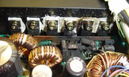
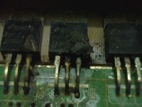
One of the IRFZ42's on one side has melted. The other side of the amp is fine and they are completely separate (practically dual mono). What I plan to do is get one of these:
http://cgi.ebay.com/ws/eBayISAPI.dll?ViewItem&category=4666&item=7523201348
and....
Obviously I can use a multimeter etc so any advice? or better ideas or ways of testing it?
I have never attempted to repair something like this but I would love to get it going....
One of the IRFZ42's on one side has melted. The other side of the amp is fine and they are completely separate (practically dual mono). What I plan to do is get one of these:
http://cgi.ebay.com/ws/eBayISAPI.dll?ViewItem&category=4666&item=7523201348
and....
- Swap it for the melted one
- Clean it all
- Measure values on the PCB of the surrounding resistors etc and compare to the good amp to make sure they have not been damaged etc.
Obviously I can use a multimeter etc so any advice? or better ideas or ways of testing it?
Attachments

Netlist said:I can see various capacitors screaming to be replaced and I wouldn't be surprised you'll find many bad solderings inside as well.
Why and why???? Just curious
")
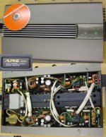
Its an Alpine Juba (very rare/expensive) and has Nichicon and Elna audio capacitors
I can't and won't comment on the qualities of the amp, but even a Rolls needs service.
Look for caps where the plastic has shrunk from the heat. Take them out and measure them.
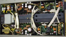
Why good luck? It looks fairly damaged although cleaning will reduce the ugly sight. Also, without schematic or experience you're on your own in this rats nest.
Anyway, aren’t we fearless amplifier builders?
/Hugo
Look for caps where the plastic has shrunk from the heat. Take them out and measure them.
Why good luck? It looks fairly damaged although cleaning will reduce the ugly sight. Also, without schematic or experience you're on your own in this rats nest.
Anyway, aren’t we fearless amplifier builders?
/Hugo
Netlist said:I can't and won't comment on the qualities of the amp, but even a Rolls needs service.
Look for caps where the plastic has shrunk from the heat. Take them out and measure them.
Why good luck? It looks fairly damaged although cleaning will reduce the ugly sight. Also, without schematic or experience you're on your own in this rats nest.
Cool, thanks.
Netlist said:
Anyway, aren’t we fearless amplifier builders?
YES!


Just follow the burnt blacknessdemogorgon said:how can you even begin to decide where to begin?

Look in my original post, I found a replacement on Ebaydemogorgon said:but more of a chalenge, how get to the parts in question?
maxw said:Hi People,
I have never attempted to repair something like this but I would love to get it going....
One of the IRFZ42's on one side has melted. The other side of the amp is fine and they are completely separate (practically dual mono). What I plan to do is get one of these:
http://cgi.ebay.com/ws/eBayISAPI.dll?ViewItem&category=4666&item=7523201348
and....
- Swap it for the melted one
- Clean it all
- Measure values on the PCB of the surrounding resistors etc and compare to the good amp to make sure they have not been damaged etc.
Obviously I can use a multimeter etc so any advice? or better ideas or ways of testing it?
It certainly doesn't look as bad as suggested...... All that black stuff is just carbon and can be easily cleaned off using alcohol.
Use IRFZ44's to replace those 'smaller' parts.
To test them, probe from pin 2(tab) to pins 1 and 3. With the fried guys still in the circuit, they will measure shorted. Once you pull them all from the circuit, when one blows you need to replace all parallel parts, you can re-measure to verify that the board is not shorted.
There are two ways to go about replacing them:
1) With the parts out, turn the amp on with some kind of current-protection, either a in-line fuse or a current-limiting power supply, and use an o-scope to probe the gate(pin1) to check for the drive wave-form(should be a square-wave). If it all looks good, pop in the new Z44s and fire her up with the current-protection.
2) Just pop the parts in a wish for the best while using current protection.
If you still have problems, than you might have a bigger issue that you may need to solve first.
Re: Re: Replacing IRFZ42 in Alpine 3558 advice needed....(pics)
Great, thanks alot TO-3. Thats just what I needed. I will have to do option 2 as I dont have access to a scope.
Cheers!
TO-3 said:
It certainly doesn't look as bad as suggested...... All that black stuff is just carbon and can be easily cleaned off using alcohol.
Use IRFZ44's to replace those 'smaller' parts.
To test them, probe from pin 2(tab) to pins 1 and 3. With the fried guys still in the circuit, they will measure shorted. Once you pull them all from the circuit, when one blows you need to replace all parallel parts, you can re-measure to verify that the board is not shorted.
There are two ways to go about replacing them:
1) With the parts out, turn the amp on with some kind of current-protection, either a in-line fuse or a current-limiting power supply, and use an o-scope to probe the gate(pin1) to check for the drive wave-form(should be a square-wave). If it all looks good, pop in the new Z44s and fire her up with the current-protection.
2) Just pop the parts in a wish for the best while using current protection.
If you still have problems, than you might have a bigger issue that you may need to solve first.
Great, thanks alot TO-3. Thats just what I needed. I will have to do option 2 as I dont have access to a scope.
Cheers!
Re: Re: Re: Replacing IRFZ42 in Alpine 3558 advice needed....(pics)

maxw said:
Great, thanks alot TO-3. Thats just what I needed. I will have to do option 2 as I dont have access to a scope.
Cheers!
Only one blown
I am still a newb, but I have already fixed a few car amps (much cheaper than buying new). I got a Kenwood KAC-959 with a broken circuit board - fixed by running wires in place of traces & a Pioneer GMX464 with blown switching fets - replaced all fets with IRFZ44. Both of them were off e-bay for a tenner or less.
Re the title, it only takes one mosfet to blow on the switching power supply to stop it working. The fets are in parallel & when one blows it becomes a dead short.(I think - remember I'm a newb)
Do replace all the fets just in case. Also be wary when powering up that the protection circuit does not kick in after a while. Once repaired the pioneer worked fine for ten minutes, then the protection circuit IC gave out completely, so even though the amp was fine, no start as it controlled the remote on function.
i have a roughly similar problem with mine. the thing is that the amp still works.. just the FETs that are blown. i replaced all 4 FETs and when i powered it up..it blew in the exact same manner.. theres something i'm missing and was wondering if anyone knows where to start?
Attachments
nickch said:i have a roughly similar problem with mine. the thing is that the amp still works.. just the FETs that are blown. i replaced all 4 FETs and when i powered it up..it blew in the exact same manner.. theres something i'm missing and was wondering if anyone knows where to start?
The oscillator chip probably needs to be replaced. The chip is blown and most likely putting out +12V to the gates of these MosFETs.
nickch said:would it be the PWM chip? TL494CN. also.. the 2 gate resistors are burnt.. and charred beyond recognition.. how am i going to replace these?
Yes the PWM is the controller chip for the power supply. The resistors should be 22 ohms, but you should be able to find another gate resistor off of the other MosFETs and find the correct value.
TO-3 said:
Yes the PWM is the controller chip for the power supply. The resistors should be 22 ohms, but you should be able to find another gate resistor off of the other MosFETs and find the correct value.
thanks.. the gate resistors of the other 2 mosfets have a value of 200 ohm (red,black, brown), would this be normal? or should i stick with your recommendation.
heres what another member on another forum diagnosed.
It was going before you took it out correct, and it still does go correct, just one of the fets has blown correct?
By the looks of it there are 2 pairs of fets, 2 fets per primary winding. If the amp is still going properly, that requires that both primary windings are being driven, in which case only one of the fets per winding can be blown, which would generally isolate the fault to the fet or its directly connected traces and passive components that are not shared with the other fets.
In which case look at the PCB traces under the board and also look at the input into the gate of the mosfet.
However looking at the 3rd pic more closely, it looks like both of the gate resistor are blown, which would mean both of the mosfet are blown. PCB design wise the mosfets for a common primary winding are next to each other, if both are blown it would mean you would be down to only one of your secondary voltage rails ie + or -. In which I would ask was the amp running correctly to start with, can you test it now and see. I would suggest that whilst it may go and produce music the cones may only move in one direction relative to their at rest positions.
out of the 4 mosfets.. only 2 are causing the problems..
- Status
- This old topic is closed. If you want to reopen this topic, contact a moderator using the "Report Post" button.
- Home
- General Interest
- Car Audio
- Replacing IRFZ42 in Alpine 3558 advice needed....(pics)