Hi All,
I've been doing many little audio amplifier experiments recently.
Over a year ago I showed the circuit of my 25W class-A amplifier which was similar to a JLH class-A, but with a mirrored differential input stage in place of the original single transistor.
Someone suggested that the original must be better because its signal path contains fewer active devices. However that is not so, for mirroring reduces waveform distortion and much improves loudspeaker damping control without lengthening (slowing) the signal path.
I have since double-checked by directly comparing single transistor input with a four transistor mirrored differential: The latter is superior, especially on transients. It is also stable on sudden loud soundbursts where the single transistor allows 'cone breathing' due to imbalanced current draw. Nor is there a start-up thump, nor any bias offset to worry about.
However 25W can be found inadequate.
A couple of months back 'Lumanauw' asked about output stages that would never drop out of conduction in order for there to be no crossover distortion. I had already been working on this with the mirrored differential JLH, and this was why I suggested class-A plus class-AB plus class-B output biasing all working together.
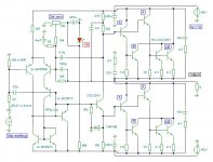
As I would never publically release any circuit that I have not thoroughly auditioned, and health problems slow me down, there has been a delay in me releasing this first circuit. It is constructed as shown in the circuit.
My simulator stores a 200W-4 ohm version of this which uses no more than four additional BC547C with 50V power rails, but I have so enjoyed listening to this that I have been slowed even more. Slowly but surely this project is advancing nicely.
Nominally this No1 circuit is for a 50W-8 ohm amplifier, but it sounds even louder on 4 to 8 ohm loudspeakers, and it is not damaged by low impedance loading which can cause smoothed psu current draws of 7A from both rails. The strange thing is that my simulator shows the circuit as being incapable of producing even 40W, so if anyone is inspired to simulate it on their own computer I would be most interested in reading their findings.
The sound is clean - I can't write more, because that's it.
If the source signal is sweet - - - If the source wavefronts slam - - -
I equate the output as being similar to 2x KT88 in ultralinear AB1, which normally sound louder than 50W solid state anyway, though unlike a valve design the bass is completely unphased at LF.
Like the original JLH class-A and my 25W circuit, this one has a low first cycle distortion characteristic because there are no parallel path capacitors pulling the open loop bandwidth down at audio frequencies, something that can arise in most other NFB designs.
This tested circuit is not yet thoroughly optimised, but it works well and is presented here as yet another variation amongst the many already available.
Cheers ........... Graham.
I've been doing many little audio amplifier experiments recently.
Over a year ago I showed the circuit of my 25W class-A amplifier which was similar to a JLH class-A, but with a mirrored differential input stage in place of the original single transistor.
Someone suggested that the original must be better because its signal path contains fewer active devices. However that is not so, for mirroring reduces waveform distortion and much improves loudspeaker damping control without lengthening (slowing) the signal path.
I have since double-checked by directly comparing single transistor input with a four transistor mirrored differential: The latter is superior, especially on transients. It is also stable on sudden loud soundbursts where the single transistor allows 'cone breathing' due to imbalanced current draw. Nor is there a start-up thump, nor any bias offset to worry about.
However 25W can be found inadequate.
A couple of months back 'Lumanauw' asked about output stages that would never drop out of conduction in order for there to be no crossover distortion. I had already been working on this with the mirrored differential JLH, and this was why I suggested class-A plus class-AB plus class-B output biasing all working together.
As I would never publically release any circuit that I have not thoroughly auditioned, and health problems slow me down, there has been a delay in me releasing this first circuit. It is constructed as shown in the circuit.
My simulator stores a 200W-4 ohm version of this which uses no more than four additional BC547C with 50V power rails, but I have so enjoyed listening to this that I have been slowed even more. Slowly but surely this project is advancing nicely.
Nominally this No1 circuit is for a 50W-8 ohm amplifier, but it sounds even louder on 4 to 8 ohm loudspeakers, and it is not damaged by low impedance loading which can cause smoothed psu current draws of 7A from both rails. The strange thing is that my simulator shows the circuit as being incapable of producing even 40W, so if anyone is inspired to simulate it on their own computer I would be most interested in reading their findings.
The sound is clean - I can't write more, because that's it.
If the source signal is sweet - - - If the source wavefronts slam - - -
I equate the output as being similar to 2x KT88 in ultralinear AB1, which normally sound louder than 50W solid state anyway, though unlike a valve design the bass is completely unphased at LF.
Like the original JLH class-A and my 25W circuit, this one has a low first cycle distortion characteristic because there are no parallel path capacitors pulling the open loop bandwidth down at audio frequencies, something that can arise in most other NFB designs.
This tested circuit is not yet thoroughly optimised, but it works well and is presented here as yet another variation amongst the many already available.
Cheers ........... Graham.
Attachments
It's complex amp  BUT really interesting. Although seems complex, it has minimal stages. I see it only has 2 stages (the VAS and output stage(s) are 1 stage?). The output stage also new to me. Class A, class AB, classB all together?
I hope AKSA will see it, cause it only use R for LTP and bootstrapped VAS. Usually this configuration sounds good (with careful matching offcourse).
What is the efficiency figure of this? How many watts audio and how many watts idle?
BUT really interesting. Although seems complex, it has minimal stages. I see it only has 2 stages (the VAS and output stage(s) are 1 stage?). The output stage also new to me. Class A, class AB, classB all together?I hope AKSA will see it, cause it only use R for LTP and bootstrapped VAS. Usually this configuration sounds good (with careful matching offcourse).
What is the efficiency figure of this? How many watts audio and how many watts idle?
Choice???
Hi Graham,
I've been following your very interesting work advancement on JLH circuitry but clearly I'm not the one to make any comments regarding the circuit operation. I will soon make a JLH and most likely will be one of your iterations that seem an excellent choice.
In the past three years I've been fooling around with Pass clones and I like the Zen with full range speakers (which is what I like to use now) but feel that JLH would be a much better amp and easy to build also.
My preferences seem to be amps with highish output impedance to drive low Qts speakers but would like some opinions regarding this statement.
If I may ask, which are your preferred speakers to drive with these JLH amps?
Hi Lumenauw,
I don't see this as being complicated and when you see how few parts there are in the actual construction it really is not so. The output resistors are on the heatsink with the 2SCs.
The mirrored differential has one BC557C in cascode to match the differential collector voltage dynamics (improves hf) also one as a simple follower to unload the first transistor of output voltage variable VAS C.bc thereby improving hf current balance within the differential pair. The fixed Cs limit closed loop gain at rf without affecting af.
Yes the 2SC3421 is an integral part of the output stage, and in this version it does not even get warm without a heatsink.
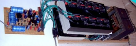
The quiescent (quietescent) heat here is 80W and the operation never drops out of class-A, but the audio output genuinely sounds like that of a conventional 80W solid state design. My heatsink is cooled by a Papst ultra-silent fan and it does not get hot, only gently warm.
The diode at the current phase splitting driver transistor is not active. It is there to prevent excessive current flow by maintaining conduction in the event of a negative power rail failure. If the upper rail goes there is no bias. My main circuit has an additional RC filter to the differential tail resistor, but the protype is working well without it !
Hi Ultima Thule,
Clearly I could have had all of the ouput transistors driven by the second class-A driver; ie. as constant class-A with class-AB boosting. This does work, BUT, all the ABs would then switch in and out of conduction at the same instant, and this can become audible due to back emf acting against NFB loop control.when the load is a dynamic loudspeaker.
However by using two differently biased class-A stages with 1 and 10 ohm emitter resistors, these are made to operate within different current ranges, thus by driving and correcting differently their efforts overlap such that one always smooths the other. Also there is no single dominant hf phase change due to Darlington drive that would otherwise degrade stability.
The separate class-B provides additional conduction for momentary power into loudspeaker impedance dips, but there are no crossover artifacts because the overall linearity is controlled by the class-A devices running within their own narrow current ranges and thus much less into conventional gain non-linearities. The class-AB and class-B currents also crossover at different cyclical time instants, so that all the class-As need do is smooth the overall characteristic. Without that class-B a NFB loop controlled correction of loudspeaker back emf induction would introduce a bigger 'wiggle'. All simulatable (but not via conventional THD/resistor testing), and as also borne out in listening tests.
Hi Apassgear,
My preference is for full range loudspeaker drivers too, but you need small ones to cover the higher frequencies, and then lots of them to go low.
In order to obviate loudspeaker back EMF induced 'wiggles' some designers go for non-feedback circuitry. I am not saying that this is wrong, but I prefer a loudspeaker sited amplifier with low output impedance drive so that a voice coil is made to follow signal waveform and limit a dynamic driver's natural overexcursions. This though is where amplifiers can come unstuck, because using NFB to correct driver modified output potential can interact with input due to amplifier propagation delay. The bipolar type of class-A circuit published by JLH is particularly good in this regard.
Cheers ............. Graham.
I don't see this as being complicated and when you see how few parts there are in the actual construction it really is not so. The output resistors are on the heatsink with the 2SCs.
The mirrored differential has one BC557C in cascode to match the differential collector voltage dynamics (improves hf) also one as a simple follower to unload the first transistor of output voltage variable VAS C.bc thereby improving hf current balance within the differential pair. The fixed Cs limit closed loop gain at rf without affecting af.
Yes the 2SC3421 is an integral part of the output stage, and in this version it does not even get warm without a heatsink.
The quiescent (quietescent) heat here is 80W and the operation never drops out of class-A, but the audio output genuinely sounds like that of a conventional 80W solid state design. My heatsink is cooled by a Papst ultra-silent fan and it does not get hot, only gently warm.
The diode at the current phase splitting driver transistor is not active. It is there to prevent excessive current flow by maintaining conduction in the event of a negative power rail failure. If the upper rail goes there is no bias. My main circuit has an additional RC filter to the differential tail resistor, but the protype is working well without it !
Hi Ultima Thule,
Clearly I could have had all of the ouput transistors driven by the second class-A driver; ie. as constant class-A with class-AB boosting. This does work, BUT, all the ABs would then switch in and out of conduction at the same instant, and this can become audible due to back emf acting against NFB loop control.when the load is a dynamic loudspeaker.
However by using two differently biased class-A stages with 1 and 10 ohm emitter resistors, these are made to operate within different current ranges, thus by driving and correcting differently their efforts overlap such that one always smooths the other. Also there is no single dominant hf phase change due to Darlington drive that would otherwise degrade stability.
The separate class-B provides additional conduction for momentary power into loudspeaker impedance dips, but there are no crossover artifacts because the overall linearity is controlled by the class-A devices running within their own narrow current ranges and thus much less into conventional gain non-linearities. The class-AB and class-B currents also crossover at different cyclical time instants, so that all the class-As need do is smooth the overall characteristic. Without that class-B a NFB loop controlled correction of loudspeaker back emf induction would introduce a bigger 'wiggle'. All simulatable (but not via conventional THD/resistor testing), and as also borne out in listening tests.
Hi Apassgear,
My preference is for full range loudspeaker drivers too, but you need small ones to cover the higher frequencies, and then lots of them to go low.
In order to obviate loudspeaker back EMF induced 'wiggles' some designers go for non-feedback circuitry. I am not saying that this is wrong, but I prefer a loudspeaker sited amplifier with low output impedance drive so that a voice coil is made to follow signal waveform and limit a dynamic driver's natural overexcursions. This though is where amplifiers can come unstuck, because using NFB to correct driver modified output potential can interact with input due to amplifier propagation delay. The bipolar type of class-A circuit published by JLH is particularly good in this regard.
Cheers ............. Graham.
Hi graham,
now I realize how your output works and have more questions.
I wonder if the dramatic current gain changes when some of the class AB or B output transistors "switch in" would change the current drive signal for the class A transistors, because as soon as the current demand at the output growes there will be an exponential current gain when those class AB and B comes into play, I feel the FB mechanism have to adopt to a nonlinear currentgain drive fo the class A transistors which acts both output as well driver transistors, yes/no?
Spreading out the the working point on several output transistors gives smaller changes at a time each one break in but I wonder if not the higher harmonics will show up more but the overall harmonics level will be lower because of each output transistor have a small contribution?
Well, this is not an easy question, just speculating here!
Regarding the casode transistor at the diff stage, I was puzzled what it should do beacause I couldn't guess if there where some "speciall issue" more than it would give a symmetrical/simmilar voltage change at the both diff-stage transistors collector.
But now when I read your answer to Lumanauw you said "(improves hf)", but I don't follow this as the voltage now at both collectors are actually counteracting against both the input voltage as well as the feedback input voltage, am I missing something here?
Regards Michael
To me this looks like a more refined (i.e. improved) version of the Edwin amplifier, isn't it ?
Regarding the "never switching off" amplifier there was once a circuit in the "circuit ideas" section of EW+WW that was called "low power class A" by Jeff MacAulay (spelling ?
). The published example had only very low power, best suited for headphones (and it was using OP-AMPs). This could very well be adapted for higher power using discretes. The main principle is that only one of the two NPN ouput transistors is within the voltage NFB loop. The other one is within a current control loop taking care that there is always a minimal common current (don't know a better expression, maybe someone else knows a better one, in German it would be called "Querstrom") flowing through both series connected transistors. IMO it would be best called single-ended class AB.
I once made simulations with a discrete version using old-fashioned MOSFET models as output devices. Simulated (!) THD was very low for low drive signals. THD is slowly rising with output swing, with 2nd order being dominant.
Regards
Charles
Graham,
I have to admit I am unsure of how your output stage works... looks interesting...
I see that you are calling for 10 x 2SC3281 in the "AB" section per rail. I presume these are large high power output devices...
Is that the sum total of all the devices labeled A, B, AB? or just the AB section? or the B and AB sections, and then how is this distributed?
Then, I notice that the quiescent current is 1 amp per rail at 42 vdc...
Which part of the "output" stage is drawing what?
At only 100ma per "AB" device, that's 1 amp. Assuming 10...
So, where are the "switch over points" for each device?
In the actual unit, is the set zero pot sufficient to maintain DC offset stability and for output bias stability??
I guess the neat part of this design is that you don't need a critical voltage/current Vbe multiplier (or similar) to set up the bias point(s)? You can just set the values for a nominal "Class A" bias for the first "A" transistor and not worry too much about it's operating point since it runs out of steam anyhow, and the AB stage takes over?? The "B" device is a "B" device since it doesn't have enough bias... the second A device has the 10 ohm which makes the AB section have bias... Is that the idea?
Did you test the output impedance/DF?? does it vary with output level?
jpeg of the beast??
_-_-bearawprint"
I have to admit I am unsure of how your output stage works... looks interesting...
I see that you are calling for 10 x 2SC3281 in the "AB" section per rail. I presume these are large high power output devices...
Is that the sum total of all the devices labeled A, B, AB? or just the AB section? or the B and AB sections, and then how is this distributed?
Then, I notice that the quiescent current is 1 amp per rail at 42 vdc...
Which part of the "output" stage is drawing what?
At only 100ma per "AB" device, that's 1 amp. Assuming 10...
So, where are the "switch over points" for each device?
In the actual unit, is the set zero pot sufficient to maintain DC offset stability and for output bias stability??
I guess the neat part of this design is that you don't need a critical voltage/current Vbe multiplier (or similar) to set up the bias point(s)? You can just set the values for a nominal "Class A" bias for the first "A" transistor and not worry too much about it's operating point since it runs out of steam anyhow, and the AB stage takes over?? The "B" device is a "B" device since it doesn't have enough bias... the second A device has the 10 ohm which makes the AB section have bias... Is that the idea?
Did you test the output impedance/DF?? does it vary with output level?
jpeg of the beast??
_-_-bear
awprint"Hi Michael,
Yes there is an increase in current gain, and that increase is very much related to load current demand, but what this means is that there is less of a decrease in NFB loop controlled linearity when compared to a normal scenario.
Distortion increases less with increasing load current than is normally the case, it also tends to be second harmonic in nature.
I show a quiescent of 1A, with half of this passing through the first class-A driver, and 1/6th each between the second class-A driver and the AB outputs, but the amplifier still sounds good when idling at 500mA when the AB outputs are passing but a few milliamps, there is then less of a maximum drive.
The higher frequency harmonics do not appear to come up, and I put this down to the principle of operation for this kind of output stage - - - the drive to one half cannot limit or affect ongoing drive to the other half, as can happen with a common VAS driven complementary output stage.
The half that is conducting most strongly tends to be NFB loop error corrected by the half that is working less hard !!!
The differential stage works better (whether there is a mirror or not) when both collectors have very similar potentials - alternating as well as dc. This must have something to do with internal activity within the second differential transistor with its low impedance connections, and is good for a 3dB improvement in loudspeaker damping without incurring phase shift penalties, as well as isolating the mirror from second transistor C.bc, which improves hf performance. Maybe this slight improvement does not arise when the differential has emmitter resistors - I don't use this arrangement and don't know.
I tried this amplifier without any input capacitor, without the 22pF capacitor plus 22 ohm resistor, and without the 4,700uF NFB capacitor. It ran exactly the same and had a frequency response from DC to RF. I actually tried it out driving an AM radio and it did amplify beyond 1.6MHz without instability. However, without the 22pF and 22ohm resistor it was capable of amplifying house wiring interference, whilst what may have been transistor flicker noise kept the output potential from ever accurately settling to zero.
Hi Charles,
I am not aware of the Edwin amplifier by name. I have seen many circuits, but to me they are like the faces of people I meet - I'm not good with names.
There have been several 'never switching off' amplifier circuits that purport to maintain low level class-A operation, but most of them rely upon output stage current or voltage sensing. Few designers appear to consider what happens when dynamically induced loudspeaker back EMF shifts the resultant output stage current to become out of phase with the incoming audio waveform. If the Jeff Macaulay circuit you mention is the one that had a 1 ohm sensing resistor in one output half, then I would agree with your IMO; the output stage had not been tested with a dynamic load, and for that reason did not give it further thought. It has only been mentioned as a 'circuit' since then, not as an audio amplifier.
Both halves of my circuit remain actively waveform controlled (to the limits of their natural capabilities) no matter what angle the output current might be.
Hi Bear,
The total number of output devices is 10, they may be whatever is to hand. I had 10x 2SC3281.
The 'Set zero' will cover many input impedances and is quite stable.
Yes I think you've got the idea, but the class-A does not run out of steam - it remains in control.
The output impedance still changes with load. Guess I would need to double-check that to answer your question.
This is one of the earlier versions.
Cheers ............. Graham.
Attachments
Hi Thanh,
If you simply add a mirror to an existing circuit you could introduce sufficient phase change to make it unstable. This circuit was designed to use the mirror at outset; you might have needed something like my 3.3pF capacitor to make yours stable.
Cheers ......... Graham.
If you simply add a mirror to an existing circuit you could introduce sufficient phase change to make it unstable. This circuit was designed to use the mirror at outset; you might have needed something like my 3.3pF capacitor to make yours stable.
Cheers ......... Graham.
Gota be the number...
Hi Graham,
It seems odd that this innovative 50W JLH design apparently has not cought the interest it deserves, besides of been presented by a very respectable member from this forum. Would have expected to see Geoff with some comments.
On this regard I would speculate that the low interest could be the number of output devices that are necesary to make it work, maybe on this one I'm proyecting myself, good lord!!!
Graham, could you elaborate a little more on the differences you have observed between both of your circuits, the 25W of last year and this one, meaning soundwise differeces? Do you think that you could tell them apart? without clipping them of course.
Cheers...
Hi Tony,
All audio enthusiasts have their own ideas about what is good and what is not. Those who like Mosfets would not give this a second look - ditto symmetrical, etc. I myself have been exactly the same the other way round because I have worked at JLH class-As for over 30yrs and found that others did not compare, though this only within a narrow range of requirements which related to output drive capabilities. Geoff is aware of my efforts, but I have never expected him to comment because as soon as you modify a JLH - it no longer is one, and he has concentrated his efforts on archiving and freely helping those with an interest in this genre.
This AABB output stage was first applied directly to my 25W circuit of last year, which uses the differential mirror.
Audible change at non-overloading levels ? None; just an improvement in powering capability, but nothing like what I am expecting shortly, and for which the ten transistors have been used, ie. 200W of class-A controlled drive to cope with dynamically induced loudspeaker impedance dips. The circuit shown is only a successful interim step, already with the reserve necessary for satisfying listening.
Here is my point;- the three transistor JLH output stage arrangement is weak with crossover fed dynamic drivers, and it distorts at much lower levels than would be expected from a resistor measured power rating. Power reserve is where class-ABs and others always score over a traditional JLH class-A.
JLH class-As do sound good with electrostatics though, because there is much less back EMF generation from electrostatics to suck linearity out of the top output transistor. I see this is where Rod Elliott introduced an additional driver in his version of this class-A design - a viable and recommendable solution - but this arrangement remains correctly functional with class-A operation only, and cannot be used for AB driving because the output halves become dynamically imbalanced.
I have tried many ways to increase the dynamic driving capabilities of this three transistor output stage arrangement, and whilst they then become capable of much increased resistor measurable power driving, most introduce an audible degradation. My work has been interesting, complex, and on a couple of occasions smoky, but it really is not worth printing any circuits if the reproduction is not improved. The AABB addition has been my first genuine success in this regard, and there is absolutely no reason why it could not be constructed using say 10 driver transistors for a 35W-8ohm design, with 500mA quiescent current and all output stage resistor value doubled.
What I particularly like about this type of circuit is that it reproduces signal detail without sounding coarse, edgy, bright or brittle. When compared to many amps it can sound as if there is something missing, but that is until you realise there has not been anything added, and nor does it need audibly degrading stabilisation circuitry, bandwidth limiting or an output choke to achieve this.
Hi Nelson,
You had your own competent and much more powerful class-A design in the early JLH class-A days, so I am particularly looking forwards to reading your findings and results. Good, bad or indifferent !
I am aware of your 'passive' class-As which trade efficiency for irrefutable quality, and thus I believe you already have much better references for comparisons, if not the powering capabilities. I have had hot class-As, and I'm not going back there, too uncomfortable, besides - hot transformers etc. smell for ages.
Cheers ......... Graham.
[Graham,
I too have a diff pair JLH, so when I saw your post I said
S**t, F**b, Z**k, and G**g!
But I see that yours is radically different, so Cheers.] posted by Nelson Pass.
[Hi Nelson,
You had your own competent and much more powerful class-A design in the early JLH class-A days, so I am particularly looking forwards to reading your findings and results. Good, bad or indifferent !
I am aware of your 'passive' class-As which trade efficiency for irrefutable quality, and thus I believe you already have much better references for comparisons, if not the powering capabilities. I have had hot class-As, and I'm not going back there, too uncomfortable, besides - hot transformers etc. smell for ages.
Cheers ......... Graham.] posted by Graham Maynard.
So, Mr.Pass may the audience hear your expert comments, please!!
As I have said elsewhere, I particularly like the JLH for the
uniquely elegant twist in the topology. You can build good
or bad amplifiers with this, and I wouldn't be surprised if
some tube guy had thought of it first, but JLH is the first
place I saw it. I think it's interesting that the appreciation
of the JLH and its offspring does not seem to center on this,
but then topology is my prime focus.
As to Class A amps in general, since I prefer highly efficient
drivers, actual power ratings and dissipation are less of an
issue for me than you might think. Using my system for a few
hours a day results in less consumption overall than my
lawnmower, if I had one.
Re: Gota be the number...
I suspect this will be a slow burning, but long lived thread.
apassgear said:It seems odd that this innovative 50W JLH design apparently has not cought the interest it deserves, besides of been presented by a very respectable member from this forum.
I suspect this will be a slow burning, but long lived thread.
- Status
- This old topic is closed. If you want to reopen this topic, contact a moderator using the "Report Post" button.
- Home
- Amplifiers
- Solid State
- Class-AABB output stage.