There are any number of ways to do it, but yes, that will work.
Grey, in your opinion is there another more prefered method?
Me, I'd use the one 2SK389 as a single differential instead of running the two devices in parallel--more like they did in the Ono. The problem then becomes that the transconductance of the stage drops, hence the gain drops, and you have to start looking at other things, like whether you want to increase the load resistors in order to get back some of the gain, etc. You could put a P-device after the differential in order to get some gain that way, and at the same time do some level shifting (i.e. bringing the signal back to ground). Then add followers in order to beef up the output current capability...
Err, but then Wayne's original design kinda gets lost in all the reshuffling. I'm not sure that's what you'd want to do. At some point you have to make a decision as to who is designing the thing, you or Wayne. Push it far enough, and it becomes your phono stage. Nothing wrong with that, just know it going into the project.
I like the Ono/Pearl front end, but after that I tend to think of other things I'd like to try. There's nothing wrong with the Ono/Pearl, it's just that you can't put me in a kitchen well stocked with herbs and spices without me wanting to cook something.
Grey
Me, I'd use the one 2SK389 as a single differential instead of running the two devices in parallel--more like they did in the Ono.
Grey, thank you for your previous post.
Why are single JFET's preferable for differential pairs? Don't matched parallel JFET's behave like a single larger device the way (I'm told) MOSFET's do? Thanks for any insight.
The 2SK389 isn't a single JFET, it's a dual. This makes it ideal for a differential, in that the two JFETs (in a single case) have very, very similar characteristics and track together thermally.
Yes, running JFETs in parallel--whether they are single devices or dual--gives you behavior somewhat like a single, larger device. Whether that behavior is what you want is the question. In the Pearl, they use a dual device with the two halves running in parallel. In the Ono, the 2SK389 halves are used as a differential. In looking at the Pearl vs. the Ono, it seems to me that they "detuned" the Ono and simplified it a bit rather than start with a clean sheet of paper. It's interesting to look at the Pearl and try to second guess why particular choices were made in the design process. It's a good excuse to linger over a decent glass of flavored ethanol.
Grey
GRollins said:Me, I'd use the one 2SK389 as a single differential instead of running the two devices in parallel--more like they did in the Ono. The problem then becomes that the transconductance of the stage drops, hence the gain drops, and you have to start looking at other things, like whether you want to increase the load resistors in order to get back some of the gain, etc. You could put a P-device after the differential in order to get some gain that way, and at the same time do some level shifting (i.e. bringing the signal back to ground). Then add followers in order to beef up the output current capability...
Err, but then Wayne's original design kinda gets lost in all the reshuffling. I'm not sure that's what you'd want to do. At some point you have to make a decision as to who is designing the thing, you or Wayne. Push it far enough, and it becomes your phono stage. Nothing wrong with that, just know it going into the project.
I like the Ono/Pearl front end, but after that I tend to think of other things I'd like to try. There's nothing wrong with the Ono/Pearl, it's just that you can't put me in a kitchen well stocked with herbs and spices without me wanting to cook something.
Grey
Does running the output differential gain increase the overall enough to make up for not having the paralled transistors? I would expect to get at least as much going from single ended to differential.
DC offset always bothers me. My speakers have no crossovers and everything was dc coupled through the preamp and amp. But now I have transformer coupling in my preamp to handle small amounts to dc from sources.
I would love to redo the output stage and get rid of the coupling caps. This will require dual rail and either a differential or single ended with current source.I am totally convinced that the very best caps cannot compare to no caps in the signal path
George.
Okay, so you're wanting to use the differential to cure the DC offset at the output? Were you wanting differential output or single-ended?
You're going to have to do something to level shift the output back down towards ground in order to get rid of the DC coupling caps at the output. The schematic shows 19.3V offset at the output. Sadly, that will not go away without throwing more parts at the thing.
So then the question becomes: Are you willing to keep throwing transistors into the thing just to get the signal back to ground?
It will very quickly become a question of comparing evils--is a cap more or less deleterious to the signal than the transistors you'd have to use to level shift the output...well...that's something that you'll have to decide before going any further. You're headed for a fairly major reworking of the original design.
Grey
Hello all,
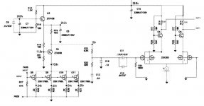
I'm planning to use the attached circuit as output stage of the Pearl phonostage (right after the RIAA eq.).
The circuit seems to be working OK according to the simulator. The next step would be to start testing in the real life, but before I start I would like to hear some opinions of people that might have already built something similar (or just are more experienced than me).
Thanks
Xavier
Attachments
I did something like this ...
Well, at least I considered doing it.
In the end i went another route and used 8 single JFET's in parallell single ended mode - i.e much the same way as the original.
What clinched it in the end for me is that since the input voltage is so low, what you get out of a balanced topology is 2 inputs with half the voltage swing each. If you use the same number of transistors (or more like I did), you can keep the load resistance the same and raise the supply voltage for higher gain, and you get "more direct" noise cancellation across devices rather than having to rely on differential noise cancellation which should work in theory, but ....
If you look at say the Ono schematics, you will find that balanced conversion takes place as a later stage. Since the Ono has too low gain anyway, you really need the extra stage unless you have a high output pickup.
Most people who know me know of my preference for balanced topology. However, even I would advice against balanced input phono stage.
The main problem with a phono stage is low input level and need for extremely high gain. I agree that it is nice to consier the input balanced - it is even floating but if you get double the voltage on the gate you will get lower noise. 60-80dB gain prior to RIAA equalization is a lot, and a little noise gets amplified extensively ...
But don't take my word for it - build both and report your results back to us!
Petter
Merge your current sources to 1
Xavier,
Consider merging your current sources to 1 and also review my prior posting so you know what you are up against.
Good luck and keep us posted!
Petter
Xavier,
Consider merging your current sources to 1 and also review my prior posting so you know what you are up against.
Good luck and keep us posted!
Petter
xavier1000 said:Hello all,
I'm planning to use the attached circuit as output stage of the Pearl phonostage (right after the RIAA eq.).
The circuit seems to be working OK according to the simulator. The next step would be to start testing in the real life, but before I start I would like to hear some opinions of people that might have already built something similar (or just are more experienced than me).
Thanks
Xavier
Petter,
Thanks for your reply. I went through your prior post very quickly this morning. I will make a deeper review tonight at home.
After reading that post, I realized that some further explanation on what was the overall phonostage were required, since the circuit I posted was just the output stage. I am attaching a block diagram to show the big picture.
All the blocks are single ended, except the mentioned output stage, where (by using two differential circuits in parallel and having one of the two inputs connected to ground) the balanced signal is generated.
Xavier
Attachments
Petter,
I believe that your initial post is considering a balance operation from the input. In the circuit that I am planning to build (see the block diagram in my previous post), the balance conversion takes place at the output stage. This stage corresponds to the schematic I posted.
I updated the circuit with more labels (input, out- and out+) to put things in a clearer way.
Originally posted by Petter
What clinched it in the end for me is that since the input voltage is so low, what you get out of a balanced topology is 2 inputs with half the voltage swing each. If you use the same number of transistors (or more like I did), you can keep the load resistance the same and raise the supply voltage for higher gain, and you get "more direct" noise cancellation across devices rather than having to rely on differential noise cancellation which should work in theory, but ....
If you look at say the Ono schematics, you will find that balanced conversion takes place as a later stage. Since the Ono has too low gain anyway, you really need the extra stage unless you have a high output pickup.
Most people who know me know of my preference for balanced topology. However, even I would advice against balanced input phono stage.
The main problem with a phono stage is low input level and need for extremely high gain. I agree that it is nice to consier the input balanced - it is even floating but if you get double the voltage on the gate you will get lower noise. 60-80dB gain prior to RIAA equalization is a lot, and a little noise gets amplified extensively ...
Attachments
I finally built a quick prototype in a veroboard to test the circuit in real life.
I connected from the Pearl after C12/C11 (i.e. after the passive RIAA stage) to the input of the circuit and one of the outputs to the preamp (the other one was left disconnected).
The two 2sk389 that were used were not matched, but were from the same lot. The source voltages were 245mV and 292mV.
I had to reduce the negative rail in order to avoid the Q14a and Q14b getting too hot.
The circuit was working OK, although a little bit noisier than the standard one, probably due to the resistor I finally added to reduce the negative rail and the overall impedance of the current sources.
The gain was also reduced by 3-4 dB compared to the other channel (that was untouched).
The sound was not bad, but I need to do some tunning and work specially in the current source.
Xavier
Consider making R1 about 100K to match the left half. In fact it should be 100 Ohms + 100K in parallell with the Pearl output impedance. 100 Ohms will set up a dynamic imbalance in the output stage.
Sorry for my earlier assumption about where you were planning to use the balanced circuitry.
I also believe you can find some further motivation if you can dig up Pass service manuals for the old phono stage which also had differntial output, but as far as I can recall the output stage was done in a less elegant way than you are doing. The service manuals are as per another post no longer available on the passlabs website. I might have a backup somewhere - not sure.
Petter
Thanks for your reply Petter. Regarding the old phono stages service manuals, I only have the Ono. In case you have a differnet one, I would appreciate if you could send me an email.
The next week-end I will continue testing. I plan to make the following improvements to the initial circuit:
- Substitution of the two jfet current sources by one current source (bipolar+led) providing 18-20 mA
- Put an additional 100K resistor in series with R1
- Additional filter stage for positive rail in order to reduce psu noise and to reduce the voltage in the jfets down to about 6v (to reduce noise)
- Additional filter stage for negative rail in order to reduce psu noise and to reduce the voltage available for the current source to reduce the heat of the transistor
- Increase R14a and R14b from 1.2k to 1.5k to raise gain.
After increasing R14, will I have problems with the resulting output impedance when plugging the output to an Aleph P1.7 (10k input impedance)?
I assumed that since I'm using an active current source, the THD will be less than when using a resistor (like in the standard Pearl). Is this assumption correct? Is it feasible to expect a distortion less than 0,1% with an output level of about 700-800mV using this circuit?
Any comments are highly appreciated.
Xavier
This is the latest version of the circuit after the changes. The sound is really good without loosing the character of the Pearl. In fact when using it as single ended output, I simply cannot distiguish between channel A (a standard Pearl) and channel B (a Pearl using this differential circuit instead of the standard output stage).
The most important change is the usage of a new CCS instead of the two jfet separate CCS. The improvement was quite noticeable.
There is still a small hiss when I turn the volume to max due for sure to the usage of a veroboard and P2P connections. The next step would be to put the circuit in a PCB.
Please feel free to comment possible improvements on this circuit.
Xavier
Attachments
Help requested for pcb design
I'm now working on a PCB for this circuit. I plan to put the board on top of the Pearl (on the right hand) and remove the current components of the standard output of the Pearl.
The schematic used for this differential output stage is the circuit posted above, with an additional filtering stage for the negative rail (similar to the one in the positive rail).
The board I am working is attached below. Please keep in mind that this is my first pcb design. I would appreciate the guidance of someone more expert.
Thanks
Attachments
xavier1000
Are you going to make the pcb able to combine the balanced output with the mc stage you mentioned in this tread: http://www.diyaudio.com/forums/showthread.php?postid=815625#post815625
Or is it two diff projects ?
I know the mc stage is for input and the balanced out is for the out
Would sure be nice with a pcb which included the two projects and possibilities
PS: Your board looks nice.
- Status
- This old topic is closed. If you want to reopen this topic, contact a moderator using the "Report Post" button.
- Home
- Amplifiers
- Pass Labs
- A differential output PEARL... ...?