Hi there,
Perhaps some of you remember the Spice simulations I posted concerning the various supply decoupling configurations of digital ICs. These simulations concerned the impedance of the bypass network, mainly based on Pete Goudreau's triplet, and its possible improvements.
But simulations don't tell the whole story, and I wanted to go a little bit further by making measurements. The problem is I don't have access to a network analyzer to measure impedances of bypass configurations. But I had the opportunity to use a spectrum analyzer. Thus I designed a little circuit which allowed me to measure the noise spectrum on the supply pin of a digital IC.
Basically, the circuit is composed of a canned 50MHz crystal oscillator, driving an 8-bit divider, namely a SMT 74HC393 in SO package. Both the XO and the 393 have their own regulators (78L05), which are fed by two 9V dry cells, the only supply common point being the ground. The PCB I designed provides room to test different packages for decoupling caps around the 74HC393. Noise on the 393's supply is monitored by the spectrum analyzer though two SMA coaxial connectors : one on the supply pin of the IC (output ot the regulator) and the other on the reg's input. The inputs of the regulators are decoupled with a 220nF/X7R/0805 on the solder side. The PCB drawing is attached here, and the story goes on on next post")
Perhaps some of you remember the Spice simulations I posted concerning the various supply decoupling configurations of digital ICs. These simulations concerned the impedance of the bypass network, mainly based on Pete Goudreau's triplet, and its possible improvements.
But simulations don't tell the whole story, and I wanted to go a little bit further by making measurements. The problem is I don't have access to a network analyzer to measure impedances of bypass configurations. But I had the opportunity to use a spectrum analyzer. Thus I designed a little circuit which allowed me to measure the noise spectrum on the supply pin of a digital IC.
Basically, the circuit is composed of a canned 50MHz crystal oscillator, driving an 8-bit divider, namely a SMT 74HC393 in SO package. Both the XO and the 393 have their own regulators (78L05), which are fed by two 9V dry cells, the only supply common point being the ground. The PCB I designed provides room to test different packages for decoupling caps around the 74HC393. Noise on the 393's supply is monitored by the spectrum analyzer though two SMA coaxial connectors : one on the supply pin of the IC (output ot the regulator) and the other on the reg's input. The inputs of the regulators are decoupled with a 220nF/X7R/0805 on the solder side. The PCB drawing is attached here, and the story goes on on next post
Attachments
Still here ?
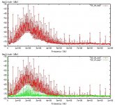
I began to make measurements with the simpliest and widely used decoupling scheme : a 100nF/25V/0805/X7R cap, and the results were quite awful (top curve of the attached image). All the peaks you can see are generated by the clock (50 MHz), and by all the frequencies related to the counter, down to 195 kHz (50MHz/256), and all their harmonics.... Quite a hairy spectrum I must confess I was a little bit discouraged by the view of all these frequencies on a supply line
Then I slowly moved (adding and removing small SMT caps without breaking the pads, stacking caps, etc..., is not a bed of roses ), making measurements at every step. First I added a 'lytic, three types : a Panasonic 120uF/25V/FC, a Rubycon 100uF/25V/ZA, and a Sanyo 47uF/6V3/OsCon. Globally, it didn't lead to significant improvements, but it improved a bit. To my surprise, if the Panasonic FC was sligthly worse than the others, I had hard times deciding between ZA and OsCon. Curves were pretty close to each other, and the highly praised OsCon was not so good (in this application) I finally settled on the ZA, mainly because if I have to use a lot of them, they cost far less .
Now keeping the Rubycon ZA on the PCB, I stacked a 10nF/X7R/0805 on the top of the 100nF/X7R/0805. Nothing significant. Removed both of them, and replaced 'em by 100nF/X7R/0612 (first) and 10nF/X7R/0612, which was stacked on the top of the previous after measuring the 100nF alone. For people who haven't read the previous posts, these are 1206-sized SMT caps, but with the long side metallized. They are characterized by a much lower inductance. Yeah ! The spectrum region above 450MHz showed nice improvements.
Finally, I added the 22uF/10V/Y5V/1210 high-value ceramic cap from Murata. Wow !! Couldn't believe my eyes the first time I plugged the circuit in the analyzer... I checked the circuit with a scope, everything was OK. I even removed the cap, remeasured, soldered the cap again. Same amazement ! On the attached image, the bottom curves compare the original 100nF/0805 decoupling (red curve) with the - hold your breath - 100uF/ZA // 100nF/0612 // 10nF/612 // 22uF/1210/Murata (green curve) - breathe Amazingly efficient, isnt'it ? Everything in the high-frequency region has disappeared, and the other peaks are lowered by about 30dBm...(Yes I know, I'd have to convert it to Volts, but I'm too lazy. I'll do it later, but if you can't wait, 0dBm correspond to a power of 1mW into 50 Ohms, i.e. 223.6 mV)
I now have to see if I can remove one or two of the other caps of the quadruplet without degrading noise rejection. It was planned, but I miss the time...
Well, I'm sure you'd like to see the intermediate curves, don't you ? I haven't had the time to do it, but if you're interested, I'll make a little document with all the configs I tested and the corresponding curves. If it fits the size limit for the forums, I'll post it, otherwise drop me an e-mail and I'll send it to you.
I have another PCB version in the pipeline, without the through-hole 'lytic, in order to test the efficiency of the SMT 'lytics, but, given the results I wonder if it's worth the testing.
Last thing : I have results concerning the noise at the input of the regulator, with and w/o coils, chokes and three-lead caps, but I'm falling asleep now...
Feel free to comment.
I began to make measurements with the simpliest and widely used decoupling scheme : a 100nF/25V/0805/X7R cap, and the results were quite awful (top curve of the attached image). All the peaks you can see are generated by the clock (50 MHz), and by all the frequencies related to the counter, down to 195 kHz (50MHz/256), and all their harmonics.... Quite a hairy spectrum
I must confess I was a little bit discouraged by the view of all these frequencies on a supply line Then I slowly moved (adding and removing small SMT caps without breaking the pads, stacking caps, etc..., is not a bed of roses
), making measurements at every step. First I added a 'lytic, three types : a Panasonic 120uF/25V/FC, a Rubycon 100uF/25V/ZA, and a Sanyo 47uF/6V3/OsCon. Globally, it didn't lead to significant improvements, but it improved a bit. To my surprise, if the Panasonic FC was sligthly worse than the others, I had hard times deciding between ZA and OsCon. Curves were pretty close to each other, and the highly praised OsCon was not so good (in this application) I finally settled on the ZA, mainly because if I have to use a lot of them, they cost far less . Now keeping the Rubycon ZA on the PCB, I stacked a 10nF/X7R/0805 on the top of the 100nF/X7R/0805. Nothing significant. Removed both of them, and replaced 'em by 100nF/X7R/0612 (first) and 10nF/X7R/0612, which was stacked on the top of the previous after measuring the 100nF alone. For people who haven't read the previous posts, these are 1206-sized SMT caps, but with the long side metallized. They are characterized by a much lower inductance. Yeah ! The spectrum region above 450MHz showed nice improvements.
Finally, I added the 22uF/10V/Y5V/1210 high-value ceramic cap from Murata. Wow !! Couldn't believe my eyes the first time I plugged the circuit in the analyzer... I checked the circuit with a scope, everything was OK. I even removed the cap, remeasured, soldered the cap again. Same amazement ! On the attached image, the bottom curves compare the original 100nF/0805 decoupling (red curve) with the - hold your breath - 100uF/ZA // 100nF/0612 // 10nF/612 // 22uF/1210/Murata (green curve) - breathe
Amazingly efficient, isnt'it ? Everything in the high-frequency region has disappeared, and the other peaks are lowered by about 30dBm...(Yes I know, I'd have to convert it to Volts, but I'm too lazy. I'll do it later, but if you can't wait, 0dBm correspond to a power of 1mW into 50 Ohms, i.e. 223.6 mV) I now have to see if I can remove one or two of the other caps of the quadruplet without degrading noise rejection. It was planned, but I miss the time...
Well, I'm sure you'd like to see the intermediate curves, don't you ? I haven't had the time to do it, but if you're interested, I'll make a little document with all the configs I tested and the corresponding curves. If it fits the size limit for the forums, I'll post it, otherwise drop me an e-mail and I'll send it to you.
I have another PCB version in the pipeline, without the through-hole 'lytic, in order to test the efficiency of the SMT 'lytics, but, given the results I wonder if it's worth the testing.
Last thing : I have results concerning the noise at the input of the regulator, with and w/o coils, chokes and three-lead caps, but I'm falling asleep now...
Feel free to comment.
Attachments
Thanks Gentlemen.
Well, concerning the coils/etc... I made tests without any filtering (for comparison), with a SMT ferrite choke (given for an impedance of 600R@100MHz), a 47uH SMT coil, and a 3 leaded SMT filter given for an attenuation better than 40dB above 5 MHz... Sorry, no ferrite bead, but the ferrite choke can be assumed as a bead, its transfer function being roughly the same. I will post detailed results soon, but I won't disclose any secrets by saying that the better the decoupling at the Vreg's output, the lower the noise at its input .
Well, concerning the coils/etc...
I made tests without any filtering (for comparison), with a SMT ferrite choke (given for an impedance of 600R@100MHz), a 47uH SMT coil, and a 3 leaded SMT filter given for an attenuation better than 40dB above 5 MHz... Sorry, no ferrite bead, but the ferrite choke can be assumed as a bead, its transfer function being roughly the same. I will post detailed results soon, but I won't disclose any secrets by saying that the better the decoupling at the Vreg's output, the lower the noise at its input .A little improvement
Hello, happy taxpayers.
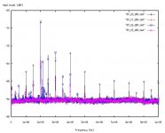
I made some additional measurements just to see the influence of each cap on the noise rejection. I've got interesting results, but the best one so far is obtained with the following configuration :
100uF/ZA // 22uF Murata // 100nF/X7R/0612 // 220nF/X7R/0805.
The latter cap is soldered on the solder side of the pcb, right on the output and GND pins of the 78L05. Results are shown on the attached picture, where the black curve is the "optimum" configuration obtained before, and the red one is the improved one.
I begin to get tired of testing caps, so I'll stop here... for the moment. I wish I could test Pete Goudreau's triplet, but I can not source any 220/270nF in 0612 package here in France (nobody's perfect ). Anyone knowing where I could buy some ?
If someone's interested in having all the curves for the configurations I tested, feel free to ask (drop me an e-mail). The document with all the stuff is too large to be posted here (pdf, 400k). Datafiles are also available if curves are too fuzzy.
Last, these are "only" measurements. I suppose it has a positive effect on the digital audio sound, but real tests are still to come. Anyone (apart from me) ? Should be nice to compare...
Enjoy.
Hello, happy taxpayers.
I made some additional measurements just to see the influence of each cap on the noise rejection. I've got interesting results, but the best one so far is obtained with the following configuration :
100uF/ZA // 22uF Murata // 100nF/X7R/0612 // 220nF/X7R/0805.
The latter cap is soldered on the solder side of the pcb, right on the output and GND pins of the 78L05. Results are shown on the attached picture, where the black curve is the "optimum" configuration obtained before, and the red one is the improved one.
I begin to get tired of testing caps
, so I'll stop here... for the moment. I wish I could test Pete Goudreau's triplet, but I can not source any 220/270nF in 0612 package here in France (nobody's perfect ). Anyone knowing where I could buy some ?If someone's interested in having all the curves for the configurations I tested, feel free to ask (drop me an e-mail). The document with all the stuff is too large to be posted here (pdf, 400k). Datafiles are also available if curves are too fuzzy.
Last, these are "only" measurements
. I suppose it has a positive effect on the digital audio sound, but real tests are still to come. Anyone (apart from me) ? Should be nice to compare...Enjoy.
Attachments
Pre-Regulator filtering...
I almost forgot
While testing various bypass configurations, I also tested some pre-regulator filtering. Reg's input was bypassed to ground by a 220nF/X7R/0805, and I removed the 22uF Murata chip to allow a higher noise level to pass through the reg towards its input.
Noise was measured on the battery, thus I monitored the noise reinjected by the reg in the supply lines. But must I add that the filtering devices work in the other way ?
The three devices I tested are from Murata, but I do not make money on them. They were :
A SMT Ferrite bead, as they call it (have you ever seen a bead with no hole ?), namely the BLM21BD601S, which is supposed to have an 600R impedance at 100MHz.
A SMT 1210 47uH coil, 1.3R DC, rated for 170mA, from the LQH32C series,
And a three-lead cap, the NFM41P, 200nF, withstanding 2 Amps (!)
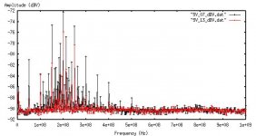
The attached pic compares these devices. Yes I know, it's a bit noisy, but try to follow the different markers. The black curve (9V_18_dBV.dat) is the noise without any filtering, the red one (9V_17_dBV.dat) is the 47uH coil, the blue one (9V_16_dBV.dat) is the chip ferrite bead, and the purple curve is the three-lead cap. It's not obvious, but all the devices seem more or less to work . The ferrite "bead" (blue/square) is the worst, it even induces resonances above the initial level(200MHz). The coil (red/cross) has a nice behavior, especially above 500MHz. My favourite is the three-leaded cap (purple/diagonal cross), which performs quite nicely (almost nothing above 500MHz). Pick yours !
One last thing. This mainly reflects the noise going through the reg from output to input, and therefore it is better to efficiently bypass the output of the reg to avoid reinjecting noise on the supply line.
We can also imagine a combination of the different devices, either in series or in //, feel free to test
Just my $0.04
I almost forgot
While testing various bypass configurations, I also tested some pre-regulator filtering. Reg's input was bypassed to ground by a 220nF/X7R/0805, and I removed the 22uF Murata chip to allow a higher noise level to pass through the reg towards its input.
Noise was measured on the battery, thus I monitored the noise reinjected by the reg in the supply lines. But must I add that the filtering devices work in the other way
?The three devices I tested are from Murata, but I do not make money on them
. They were :A SMT Ferrite bead, as they call it (have you ever seen a bead with no hole
?), namely the BLM21BD601S, which is supposed to have an 600R impedance at 100MHz.A SMT 1210 47uH coil, 1.3R DC, rated for 170mA, from the LQH32C series,
And a three-lead cap, the NFM41P, 200nF, withstanding 2 Amps (!)
The attached pic compares these devices. Yes I know, it's a bit noisy
, but try to follow the different markers. The black curve (9V_18_dBV.dat) is the noise without any filtering, the red one (9V_17_dBV.dat) is the 47uH coil, the blue one (9V_16_dBV.dat) is the chip ferrite bead, and the purple curve is the three-lead cap. It's not obvious, but all the devices seem more or less to work . The ferrite "bead" (blue/square) is the worst, it even induces resonances above the initial level(200MHz). The coil (red/cross) has a nice behavior, especially above 500MHz. My favourite is the three-leaded cap (purple/diagonal cross), which performs quite nicely (almost nothing above 500MHz). Pick yours !One last thing. This mainly reflects the noise going through the reg from output to input, and therefore it is better to efficiently bypass the output of the reg to avoid reinjecting noise on the supply line.
We can also imagine a combination of the different devices, either in series or in //, feel free to test
Just my $0.04
Attachments
Hi Francois (still haven't found out how to do the c thing on a German keyboard),
great work!!! Having just gotten back from vacation in France, I have enough extra energy to embark on a few nitpicking comments:
1) Why doesn't the oscillator can get a ceramic supply cap? Is it inside the can? Most cans I know have very insufficient internal bypassing.
2) The HC is already quite noisy. If you need an even better signal generator, go for an AC part.
3) I think the layout is suboptimal. So while I am not surprised that the caps close to pin 14 had no great influence, I am a little surprised about the effectiveness of the 22 uF cap.
Reason: the IC draws current between pins 7 and 14. The current supplied by the 100 nF caps close to pin 14 has to travel around the case to reach pin 7. Worse yet, the current supplied by the 22 uF has to travel through the ground pad of the regulator (where it mucks up its reference - a goo d thing the regulator is so slow!) and then take a detour aroung the clk pin of the can before it can reach pin 7.
You could route the signal between pins 6 and 13 around the case or on the other side of the board. This would give you a continous ground plane underneath the IC minimizing the path and hence both inductance and radiation of EMI. Then both ceramic caps should be placed where the ground and output pins of the regulator are right now so that the ground connection of the caps is right at the ground plane. Alternatively, you could use vias at pins 7 and 14 and place the caps on the other side of the board, directly underneath the IC.
The bead or 3 pin filter (which I use very frequently) belongs between the decoupling caps and the regulator, as close to the decoupling caps as possible and with the center lead of the filter touching the ground plane that extends underneath the IC. The electrolytic could be placed in the same position as the ceramics, but on the other side of the board. In your layout, the regulator, the electrolytic and the lead going to the electrolytic serve as antennae that radiate the supply noise of the IC.
4)Where did you get the 22 uF capacitor and how much were they? I have seen the ads by Murata but wasn't able to buy them anywhere. RS components used to offer 4u7 murata caps but when I tried to get them, they stayed on the backorder list for months until they were finally cancelled. The subsequent catalogs did not even contain them any more. I use Murata caps Y5V - GRM 40 in 0805 case. The largest I can get are 10 V/2u2 and 16 V/1u0. The price is reasonable, 9 and 5 Euros for a pack of 50.
Do you have any idea why they are so much more effective than your 100 and 10 nF 0612 caps? It can't be the capacitance at these high frequencies. Is the ESL, ESR so much better for the large parts?
5) SMD ferrite coil: I am a little wary of using wound coils, even if they are on a ferrite core because the interwinding capacitance capacitance will shunt the inductive and dissipative part at very high frequency. I am surprised this is not the case here. Maybe Murata found a good way to make the windings. I don't think it can be a straight pass at 47 uH.
6) Some people advocate the use of 1 nF NPO or COG caps in parallel to the 100 nF cap. Worth a try?
Curious to hear your answers!
Eric
Hi Eric,
nice to have you back. How was your trip to France ? Rainy ?
Well, 'll try to answer...
2) I've taken what I had in my junkbox. I'm not a great fan of AC chips for audio, and an HC seemed a good choice. I still wanted to have noise on the supply.
1 & 3) I've only shown the visible face of the iceberg. The pcb is double-sided, with an almost complete ground plane underneath. The XO has a 100nF/X7R/0805 right on its supply pin, and the 120uF, which is also connected to the XO's reg output, is bypassed by a 220nF/1206. Otherwise, I agree, the layout is suboptimal, mainly because I wanted to have some room to be able to solder and desolder, and my iron's tip must find its way, and my fat fingers too. I know, it's not the best for minimizing inductances and paths, but I had to make some compromissions . Somehow, I don't know if you have counted the following direct ground connections from topside to bottom groundplane : ground of regs, ground of HC's electrolytic, ground of XO (near pin 7), those last two being metallized through-holes. I was reluctant to add a via to pin 14, since it adds inductance, which I had already too much.
I've not tested the ferrite bead between caps and reg. My aim was to provide the IC's supply pin with the most resistive path to ground, and adding the bead in series seems to add some inductance to reg's output impedance... But it's worth testing.
4) Got the 22uF from Radiospares in France (www.radiospares.fr) Reference 312-3128, for 15 Euros (excluding VAT) the bunch of ten, or 1.5 Euros each. Yes, it's a little bit pricey, but far less than an OS-Con. I think that their performances is due to their low inductance, below 1 nH. Yes, I know, 0612 do have a low ESL too, but the high cap value of the Murata helps to remove the resonances of the small caps, and smoothes the impedance of the network. But I think the 100nF or 220nF are mandatory IMHO. I have curves where the 0612 caps have been removed, leaving the 100uF/ZA and 22uF/Murata alone, and results are not that best. If you're interested, I can send you the file.
5) Don't know Just wanted to test'em since a lot a people commonly use a 47uH or 10uH coil to filter their digital supply lines.
6) Shall we try ? I'm afraid to add a high frequency resonance that can not be easily smoothed, but why not ?
Hope I've answered you...
nice to have you back. How was your trip to France ? Rainy
?Well, 'll try to answer...
2) I've taken what I had in my junkbox. I'm not a great fan of AC chips for audio, and an HC seemed a good choice. I still wanted to have noise on the supply.
1 & 3) I've only shown the visible face of the iceberg. The pcb is double-sided, with an almost complete ground plane underneath. The XO has a 100nF/X7R/0805 right on its supply pin, and the 120uF, which is also connected to the XO's reg output, is bypassed by a 220nF/1206. Otherwise, I agree, the layout is suboptimal, mainly because I wanted to have some room to be able to solder and desolder, and my iron's tip must find its way, and my fat fingers too
. I know, it's not the best for minimizing inductances and paths, but I had to make some compromissions . Somehow, I don't know if you have counted the following direct ground connections from topside to bottom groundplane : ground of regs, ground of HC's electrolytic, ground of XO (near pin 7), those last two being metallized through-holes. I was reluctant to add a via to pin 14, since it adds inductance, which I had already too much.I've not tested the ferrite bead between caps and reg. My aim was to provide the IC's supply pin with the most resistive path to ground, and adding the bead in series seems to add some inductance to reg's output impedance... But it's worth testing.
4) Got the 22uF from Radiospares in France (www.radiospares.fr) Reference 312-3128, for 15 Euros (excluding VAT) the bunch of ten, or 1.5 Euros each. Yes, it's a little bit pricey, but far less than an OS-Con. I think that their performances is due to their low inductance, below 1 nH. Yes, I know, 0612 do have a low ESL too, but the high cap value of the Murata helps to remove the resonances of the small caps, and smoothes the impedance of the network. But I think the 100nF or 220nF are mandatory IMHO. I have curves where the 0612 caps have been removed, leaving the 100uF/ZA and 22uF/Murata alone, and results are not that best. If you're interested, I can send you the file.
5) Don't know
Just wanted to test'em since a lot a people commonly use a 47uH or 10uH coil to filter their digital supply lines.6) Shall we try ? I'm afraid to add a high frequency resonance that can not be easily smoothed, but why not ?
Hope I've answered you...
In that case vias close to pin 7 and the ground connections of all caps would seem adequate. At the same time you could probably cut the connections to the topside ground.
I don't quite get the point about a via close to pin 14 resulting in higher inductance. A typo?
Cheers,
Eric
I don't quite get the point about a via close to pin 14 resulting in higher inductance. A typo?
Cheers,
Eric
capslock--
Why an NPO cap in parallel? What is magic about NPO? I've read very little about the effect of various ceramic dielectrics on bypassing efficacy, other than the obvious tempco and voltage coeficients.
Dr. Johnson says that one should use "the largest capacitance you can afford in a given package, since your ESL will be a function of package size at high frequencies"--does this mean high capacitance really does matter, even at high frequencies? I must say I don't understand it.
If you can order from Digikey they stock a number of 5-22uF ceramics in various small package sizes. The 0612 are harder to find than 0805, 1206, 1210.
====
Francios--
Do you feel that the presence and location of the bulk aluminum is of importance? When designing my board I've been stacking 0805 (100nF X7R / 3.3uF X5R) in parallel with a 1210 pad, on which I'm placing a 10uF X5R. (should be about the same as 22uF Y5V at Vcc=5V) But, I did not include bulk caps after the reg, thinking that large valued caps would not be of much use. Is this a bad idea, given your testing?
I'd be thrilled if you would email me your results.
better bypass caps on the way
Check out this article:
http://www.nikkeibp.asiabiztech.com/nea/200201/cmpo_162476.html
polymer and large value ceramic caps are proliferating.
ftorres: you're a gem, thanks for the data. You're a fast worker.
Just curious: what about those clocks in a typical cd player - what
are the best combinations of caps/ferrites/chokes. etc?
I made some measurments some time ago and recall that
the bias voltage on the ceramic caps do not affect their
bypassing ability ie their impedance vs freq curve still looks
the same with or without a bias voltage. I did not measure
the electrolytics or tantalums though, and I would assume
that the impedance vs freq characteristics of these latter ones will be affected by bias across them.
cheers
NPO
Tiroth,
I agree with you fully that there is no need for the high linearity of the NPO substrate in this application. I am not even sure that there is any benefit to adding a 1 nF capacitor but I have seen it advocated and implemented many times (which does not prove that it is indeed beneficial in any way...).
If there are any advantages then these are due to the low dielectric constant of NGO which makes it necessary to use an unusually high number of metallized layers per nF. This in turn might reduce the ESL.
Still this is no more than handwaiving which is why I suggested the experiment which would either vindicate or dispell this myth.
Eric
Seems I've opened Pandora's box Everybody has its own configuration to test
Tiroth: I guess the big 'lytic cap destroys the harmony of your PCB More seriously, thanks for pointing it out. I did not take the time to remove this cap to see what was its influence, but I will try shortly (tomorrow), along with a small NPO cap (for capslock), just to see, since I'm naturally curious. However, "a priori", I think this cap helps a lot at low frequencies, where it combines with the high-value ceramic to provide efficient filtering here. In your particular case, no need to remind you that you will have 192kHz peaks on the supply line. And if the electrolytic can not be avoided, try to locate it the closest to other caps, to minimize the trace inductance from this cap to the others. And if possble, use metallized through holes to connect it, to lower the leads' inductance.
Yves: Thanks for your kind comments, but I didn't do something special. I just had the facilities to make some tests, and I was despicably interested for my future designs. Re. your question about CD players clocks, I do not have a readymade answer, but I think the given bypassing scheme should apply. Mostly depends on how the digital section works (oversampling or not), but if we talk of a "classical" DAC, 16 bits, 44.1kHz with 8x oversampling, ie with a clock between 11MHz and 17MHz, we should emphasize on the "intermediate frequency" decoupling, with the addition of some 100nF-range caps. What comes to mind is to replace the 220nF/0805 by a 470nF/0805, it should help in the aimed frequency range. Re. Coils and choke, the NFM41P seems to do a good job, thus I'd keep it.
I too looked at the datasheets for the influence of the bias voltage. It do not seem to affect a lot the resistive/inductive part of ceramic caps, and mainly acts on the capacitance (The Murata is the worst at this job!)
Thanks also for the interesting article on the future of caps. Very impressive figures, and good news for us, provided we can source some of these little marvels. I think I'll keep my little PCB to make some tests again in a year or two...
Everybody has its own configuration to test Tiroth: I guess the big 'lytic cap destroys the harmony of your PCB
More seriously, thanks for pointing it out. I did not take the time to remove this cap to see what was its influence, but I will try shortly (tomorrow), along with a small NPO cap (for capslock), just to see, since I'm naturally curious. However, "a priori", I think this cap helps a lot at low frequencies, where it combines with the high-value ceramic to provide efficient filtering here. In your particular case, no need to remind you that you will have 192kHz peaks on the supply line. And if the electrolytic can not be avoided, try to locate it the closest to other caps, to minimize the trace inductance from this cap to the others. And if possble, use metallized through holes to connect it, to lower the leads' inductance. Yves: Thanks for your kind comments, but I didn't do something special. I just had the facilities to make some tests, and I was despicably interested for my future designs
. Re. your question about CD players clocks, I do not have a readymade answer, but I think the given bypassing scheme should apply. Mostly depends on how the digital section works (oversampling or not), but if we talk of a "classical" DAC, 16 bits, 44.1kHz with 8x oversampling, ie with a clock between 11MHz and 17MHz, we should emphasize on the "intermediate frequency" decoupling, with the addition of some 100nF-range caps. What comes to mind is to replace the 220nF/0805 by a 470nF/0805, it should help in the aimed frequency range. Re. Coils and choke, the NFM41P seems to do a good job, thus I'd keep it.I too looked at the datasheets for the influence of the bias voltage. It do not seem to affect a lot the resistive/inductive part of ceramic caps, and mainly acts on the capacitance (The Murata is the worst at this job!)
Thanks also for the interesting article on the future of caps. Very impressive figures, and good news for us, provided we can source some of these little marvels
. I think I'll keep my little PCB to make some tests again in a year or two...parts and sources
Hi Francois,
small wonder the Rubycon ZA was better than the Panasonic FC. Series resistance is roughly 4x smaller for similar voltage and capacitance. Where did you get them? In Germany, only Farnell caries them at a STEEP price and they will only ship to businesses.
For the Murata 0612 chip, they will state low ESR in their PDF ceramic chip catalogue, but no values. Still they seem interesting. Not even radiospares.fr carries them, so where was your lucky hit?
As for the Murata high capacitance parts, strangely, radiospares.fr carries them but not their German sister company rscomponents.de! The GJ2 series is officially only for reflow soldering so there is a certain risk of damaging them with a soldering iron.
A better choice seem to be the GRM31 and GRM21 parts further down the same page which may be hand soldered. The 16V/4u7 part is even cheaper in this series than in the GJ2 series. ESR, ESL performance seems to be equivalent, but one cannot really tell as they don't compare parts with identical rating from the two series.
Considering that Y5V maintains only 35% of it rated capacitance at half the rated voltage, a lower value with a higher voltage rating may be the better choice for 5 V applications.
I am beginning to wonder what an Y5U cap is going to do on the reference decoupling pin of a DAC, but that is for another post...
Eric
Joy of sourcing
The show must go on...
I sourced Rubycon/ZA from Farnell/France (who can also supply parts to "ordinary" people, provided you ask them to open you an account). Dunno about the price in Germany, but its about 1 Euro each. Yes, a bit expensive, but not when compared to OS-CONs, twice or three times the price for about the same performances. But as I plan some little additional tests (I'm a beast of burden) , I will try to reverse to Panasonic FQ (much much cheaper), just to see... I settled on the ZA before having added the 1210 ceramic cap, so who knows ? If we can save money here, that's good news ! I'm pretty confident that it won't be better or worse. I think this cap has to be here, but that its performances have not to be awesome to achieve nice results for the global network. Stay tuned
0612 Caps are not Murata's (surprised, hu ?), nor from AVX (couldn't source any of this makes in France), but from Phycomp Components, who also provides a free tool to plot caps' characteristics. As a side note, they rate their 0612 caps for a lower ESL than AVX's (0.4nH if memory serves)
Despite being given for reflow soldering, I had no problems with the 22uF being hand-soldered, provided you're quick enough, but I didn't resolder the parts I desoldered, I used new ones.
The capacitance change of the 22uF with bias voltage still annoys me, and Dr. Capslock may be right. The smaller and cheaper value (4.7uF/16V/1206/X7R) is another thing to try
Just to tell you how this story began, have a look here, which I found by accident while wandering on the net. The low inductance properties (page 5) of the Murata cap jumped straight at my face In fact, I haven't been able to dig out an inductance value for this kind of cap anywhere, except here... Hints/links anyone ?
And Tiroth, could you elaborate on these 1812 F Caps (links) ?
Cheers,
The show must go on...
I sourced Rubycon/ZA from Farnell/France (who can also supply parts to "ordinary" people, provided you ask them to open you an account). Dunno about the price in Germany, but its about 1 Euro each. Yes, a bit expensive, but not when compared to OS-CONs, twice or three times the price for about the same performances
. But as I plan some little additional tests (I'm a beast of burden) , I will try to reverse to Panasonic FQ (much much cheaper), just to see... I settled on the ZA before having added the 1210 ceramic cap, so who knows ? If we can save money here, that's good news ! I'm pretty confident that it won't be better or worse. I think this cap has to be here, but that its performances have not to be awesome to achieve nice results for the global network. Stay tuned 0612 Caps are not Murata's (surprised, hu ?), nor from AVX (couldn't source any of this makes in France), but from Phycomp Components, who also provides a free tool to plot caps' characteristics. As a side note, they rate their 0612 caps for a lower ESL than AVX's (0.4nH if memory serves)
Despite being given for reflow soldering, I had no problems with the 22uF being hand-soldered, provided you're quick enough, but I didn't resolder the parts I desoldered, I used new ones.
The capacitance change of the 22uF with bias voltage still annoys me, and Dr. Capslock may be right. The smaller and cheaper value (4.7uF/16V/1206/X7R) is another thing to try
Just to tell you how this story began, have a look here, which I found by accident while wandering on the net. The low inductance properties (page 5) of the Murata cap jumped straight at my face
In fact, I haven't been able to dig out an inductance value for this kind of cap anywhere, except here... Hints/links anyone ?And Tiroth, could you elaborate on these 1812 F Caps (links) ?
Cheers,
Digikey lists them, but currently none in stock:
www.digikey.com, look up PCC2246 (100uF F) PCC2245 (47uF X5R)
These are panasonic's
ECJ-5YF0J107Z, 100uF/6.3V/F/1812
ECJ-5YB0J476M, 47uF/6.3V/X5R/1812
www.digikey.com, look up PCC2246 (100uF F) PCC2245 (47uF X5R)
These are panasonic's
ECJ-5YF0J107Z, 100uF/6.3V/F/1812
ECJ-5YB0J476M, 47uF/6.3V/X5R/1812
Re: Joy of sourcing
You mean Y5V, right? X7R would be too good to be true...
Maybe I can offer a couple of $0.01 on when a electrolytic is necessary. A digital IC that handles only clock signals, i.e. HF signals that do not change with the audio signal, most certainly does not require the electrolytic.
An oscillator creates only a HF signal, so its current draw has no LF component other than DC. However, a electrolytic can be desirable to filter out LF noise on the supply.
A DAC, digital filter or SPDIF receiver will have a current draw that depends to some degree on the signal, so the electrolytic is needed both to keep the rail voltage for the device stable (to avoid signal related distortion) as well as to keep this LF current draw out of the supply of other devices.
A digital IC that processes the SDATA will have some signal dependent current draw and may need the extra cap in order not to disturb other parts. Also, if it is handling a timing-critical clock (MCLK in integrated DAC, WCLK between DF and DAC in multibit designs) at the same time, the cap may be needed to avoid modulation of the gates processing the critical signal by LF supply variations. Of course, there is nothing you can do about the ESR and ESR of the supply leads within a case, so a purist might want to handle the signals in two different ICs....
A through hole electrolytic may act as an antenna so it could radiate the noise that is on the supply pins. Therefore it should not have a direct connection but rather the trace should go from supply pin to ceramic (which filters out the HF current pulses) to electrolytic. One could even argue to use a cheap high-ESL electrolytic and a small choke between the ceramic and the electolytic. The filtering action would still work up to several 10 kHz and the HF current is confined to a much smaller loop.
Eric
ftorres said:
The smaller and cheaper value (4.7uF/16V/1206/X7R) is another thing to try
You mean Y5V, right? X7R would be too good to be true...
Maybe I can offer a couple of $0.01 on when a electrolytic is necessary. A digital IC that handles only clock signals, i.e. HF signals that do not change with the audio signal, most certainly does not require the electrolytic.
An oscillator creates only a HF signal, so its current draw has no LF component other than DC. However, a electrolytic can be desirable to filter out LF noise on the supply.
A DAC, digital filter or SPDIF receiver will have a current draw that depends to some degree on the signal, so the electrolytic is needed both to keep the rail voltage for the device stable (to avoid signal related distortion) as well as to keep this LF current draw out of the supply of other devices.
A digital IC that processes the SDATA will have some signal dependent current draw and may need the extra cap in order not to disturb other parts. Also, if it is handling a timing-critical clock (MCLK in integrated DAC, WCLK between DF and DAC in multibit designs) at the same time, the cap may be needed to avoid modulation of the gates processing the critical signal by LF supply variations. Of course, there is nothing you can do about the ESR and ESR of the supply leads within a case, so a purist might want to handle the signals in two different ICs....
A through hole electrolytic may act as an antenna so it could radiate the noise that is on the supply pins. Therefore it should not have a direct connection but rather the trace should go from supply pin to ceramic (which filters out the HF current pulses) to electrolytic. One could even argue to use a cheap high-ESL electrolytic and a small choke between the ceramic and the electolytic. The filtering action would still work up to several 10 kHz and the HF current is confined to a much smaller loop.
Eric
- Status
- This old topic is closed. If you want to reopen this topic, contact a moderator using the "Report Post" button.
- Home
- Source & Line
- Digital Source
- Bypass Caps for digital IC decoupling