I have been doing some searching for a while on grounding and seem to come across some quite a few different opinions.
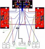
In a previous post about GC distortion, moamps proposed a better grounding scheme for BrainGT’s Kit.
http://www.diyaudio.com/forums/showthread.php?s=&threadid=41357&perpage=10&highlight=&pagenumber=1
carlosfm, in the same post noted the use of a " 0.1uf cap parallel with a 100R resistor, not directly to star ground "
What is the function of the cap and resistor? And where would they go?
Also I have read the opinion that all signal grounds should be stared, then connected to the power grounds (stared) with a high gauge wire (to prevent flow back to signal star), then using a low gauge wire to connect the power star to earth.
(Signal Star) >High Gauge> (Power star connected to chassis) > Low gauge wire > Earth
And just to add more confusion, I've read that the most important ground is from the decoupling caps to ground and that some people have two signal and two power grounds (a pair for each channel) to get short runs.
I'm building a BrianGt LM3875 NIGC and would like to know and understand the ideal grounding scheme.
When use the term "signal ground," meaning everything that would be connected to the signal star, would that included the ground from the speaker terminals? Since it carries an audio signal or is it just the ground for the input signals?
Thanks,
Matt
Attachments
Hi TheDriver41,
I can understand your dilema, but follow Brian's instructions and you will have a "dead quiet" GC. There must be hundreds of them built this way. I tried a star earth very similiar to the diagram but WITHOUT cutting the tracks and had hum. Bad mistake on my behalf. Instead of cutting the track I was going to drill a hole through it, but I already had the resistors in place.
The logic with Brian's PCB is the channels are completely separate for as long as possible, so the common earth is on the PCB not at the PSU.
On my p2p GCs, I follow Joe Rasmussen's schematics for Power and Signal earths and this also works very well.
Moamps proposed earthing scheme is very similar to most of my discrete amps and is the recommended good practice. The only difference is my signal in earths have not gone directly to star earth.
So, I would suggest build as per Brian's instructions, if you are not happy with the results, then try moamps alternative. Personally I doubt if you could notice a difference.
BTW: I didn't connected the BrianGT's PCB earth to chassis earth.
Thanks
grege said:
BTW: I didn't connected the BrianGT's PCB earth to chassis earth.
Thanks
Are you talking about the example that is "dead quite" or had hum?
Also are you talking about step 3 on page 18 of the guide, "You will also need to run a ground wire from your chassis ground to each channel."
http://www.chipamp.com/nigc_kit-users_guide.pdf
Did you just run the "PCB earth" to the earth on the mains?
Or did you just not use the "PCB earth" and ground just the chassis?
Thanks,
Matt
TheDriver41 said:
Are you talking about the example that is "dead quite" or had hum?
Also are you talking about step 3 on page 18 of the guide, "You will also need to run a ground wire from your chassis ground to each channel."
http://www.chipamp.com/nigc_kit-users_guide.pdf
Did you just run the "PCB earth" to the earth on the mains?
Or did you just not use the "PCB earth" and ground just the chassis?
Thanks,
Matt
Sorry for the confusion.
It was "dead quite" following Brian's instructions but I did NOT connect CHG to anything. Yes step 3 page 18.
For safety reasons, I always connect mains earth to chassis.

Hum problem solved/work around
One of my LM3886 BrianGT Gainclones would hum when I would connect both channels to a source. Later I learned that if I joined the right channel's signal pin to the left channel's ground on my interconnects it would hum without connecting the amp to anything. Another gainclone built exactly the same way does not have this hum.
After many hours tonight of troubleshooting, putting in a new chip in one channel, swapping the 1000uF BG caps around I finally gave up and gave each channel it's own power supply. No more hum and it seems to sound better then ever or maybe it is just that my mood has improved")
When I looked at the hum on my scope it looked odd to me. It looked like a 60 Hz sine wave with only the negative hump. Not the top hump folded down to make it 120 Hz, just the bottom hump of a 60 Hz with a flat line connecting them. Maybe this is what ground loop hum looks like, but I was expecting it to have a positive and negative content.
Anyone else have a similar experience or want to comment?
One of my LM3886 BrianGT Gainclones would hum when I would connect both channels to a source. Later I learned that if I joined the right channel's signal pin to the left channel's ground on my interconnects it would hum without connecting the amp to anything. Another gainclone built exactly the same way does not have this hum.
After many hours tonight of troubleshooting, putting in a new chip in one channel, swapping the 1000uF BG caps around I finally gave up and gave each channel it's own power supply. No more hum and it seems to sound better then ever or maybe it is just that my mood has improved
When I looked at the hum on my scope it looked odd to me. It looked like a 60 Hz sine wave with only the negative hump. Not the top hump folded down to make it 120 Hz, just the bottom hump of a 60 Hz with a flat line connecting them. Maybe this is what ground loop hum looks like, but I was expecting it to have a positive and negative content.
Anyone else have a similar experience or want to comment?
- Status
- This old topic is closed. If you want to reopen this topic, contact a moderator using the "Report Post" button.
- Home
- Amplifiers
- Chip Amps
- BrianGT LM3875 NIGC Gounding Scheme