Resume of Sony CDP players mod's “dead” thread.
Dead thread.
I am working around the output stage of a Sony CDP player XB940 SACD, the XA50/30/20 and XB940/920/720 are similar (VC24+ CXD2562Q or CXD8735N - DAC chip’s). I tested various configurations (OP-Amp’s / discrete) the last one uses a trans former to unbalance the output, but it can be used in balance mode. The sound is really very "natural" and the design is quite simple.
The first and easiest way to improve this player is to bypass the “current pulse chips”, so you get the DSD directly from the dac in a differential voltage mode, both at 2.5V dc, I think you have already seen this in a few sites (VSE, LC-Audio etc...) For the output stage, there are various possibilities : Op-Amp, discrete differential to single ended, transformer…
The goal was also to unbalance the dac outputs, to make them compatible with my preamp/crossover or at least to get the choice between balanced or unbalanced outputs.
About the current pulse converters :
Lars Clausen (In another thread) :
“This is SONY's own explanation of the Current Pulse Converter. ...
Sony’s engineers for the "Extremely high Standard" (ES) series created other decisive factors for excellent sound quality: the Current Pulse D/A Converter and R-Core Transformer. Unlike standard D/A converters, the new Current Pulse D/A Converter does not use a voltage-pulse output. Instead it operates with current-pulse output for constant signal quality. Changes in voltage amplitude (e.g. from mains fluctuations) are eliminated and harmonic distortion is minimised. The R-Core Transformer on the other hand ensures a stable voltage supply independent of load. “
My own tests on them :
The current pulse converters are very sensitive to their supply (+7,-7V) and their reference. I tested in this way, after the current pulse converters, with battery power supplies and batteries for the reference, (battery for the reference was the biggest improvement), this modification is not as effective in the reproduce sound quality as the one I describe here, and is more complicated and difficult to implement. Well… I must say that I didn’t test it with a jocko homo I/V converter...
In order to “try” the signal directly at the output of the dac, and to achieve a smooth filtering, the first and simple way, was to use a “good” op amp. The AD826 or AD828 are among the best ones for this application in my knowledge and the less tricky to implement. I prefer the AD828 (Gv>2) but the AD826 with a current sink of 5mA to V-. will give you about the same results. I didn’t tested the most recent ones from Analog Devices…
This simple mod, bypassing the current-chips and a few Burr Brown op amps improved greatly the sound in all the ways !
Here there is the diagram for picking up the balance bit stream output of the Vc24+ at the input of the “current pulse converters”. Thanks Elso, Ergo, Christer for the thread and VSE for diagram.
About the same subject :
Christer’s thread.
Out-picking.
For the output VC24+ output resistors I choose a rather high value 39 kohms. I tested 4,7k, 10k, 22k, 33k, 39k, It’s seems that high values (> 30 kohms) sound best. Difficult to say more, without the schematic of the VC24+… But now than the global design is defined I will do more accurate listening tests on it.
My first “evaluation designs :
XB-output1.
The DAC output offset between +out and –out, is not 0V but a few mV, and moreover, change according to the playing mode CD (pcm) or SACD (bit stream).
So in this second schematic I implemented a dc-servo.
XB-output2.
Extremely satisfied by these firsts improvements, I went further and carried out a very simple circuit based on fet followers.
Fet evaluation schematic.
The sound was astonishing real, natural, when you reach this degree of transparency, sometimes in some cd’s you wonder whether certain noises come from ! Your room ? Are they recorded ? Until you listen the track once more…
Following these encouraging results I refined the design to make it reliable in the player, now it includes a dc-servo. and a transformer.
Fet with dc-servo.
Fet final schematic.
Fet final schematic xfr-less.
The version I prefer, is the fet one with servo and transformer, the op amp version is not very far in terms of "very very good reproduction", but the last fet version with transformer is simply real, well... much more real.
Actually I use the transformer, to unbalance the output (my crossover input is unbalanced). I tested the schematic below, with just one "leg" the +output, and I increase R101/110 to about 390 Ohms to get 0V dc in the output. It's just a very little better than the transfo version, but unfortunately a little bit noisy, well i can hear it with my ears near the horn of my TAD's (of course, noise is cancelled in the balanced mode).
Noise in my 20 kHz FFT is at -114 dB in CD mode and balanced, about -130 dB in SACD mode.
Fet's are matched by pairs and about 9 mA of Idss.
Transfos are LUNDAHL LL5402, because I have 2 of them from an unused audio distribution amplifier, and their characteristics seems to match my requirements. I will test next days an LL7902.
I am not very qualified in transformers : brands… , low/high “copper”, amorphous… etc… Jensen’s and Lundahl seems to be good devices, as they are rather expensive I can’t make a lot of tests, so some advises are welcome.
The output impedance of the fet followers is about 30 ohms, but it's better not to load them at less than 3 kOhms.
For these first evaluations I used batteries.
I tested rather quickly an emitter and a source follower power supply (capacitor multiplying) after a schottky rectifier and an RCRC network, it seems not to be far from batteries, but I need more listening tests to go further. I will work on it after building the output stage on a pcb, and having chosen the right transformer.
I am trying too, a discrete differential input, differential/single ended output, to solve the noise and in a lesser way the filtering (in the single ended mode), as well as to get rid of the transformer. But it is for in a few weeks, for now I will continue to improve and complete this fet design, and use it later as reference.
Elso :
“Many things could be done to improve the Sony: powersupply, bypassing, other opamps etc. etc. The many SMD parts discourage me from doing it…”
Yes I know… But the modification is worth the sorrow! And with a dedicated pcb, just 8 wires from the dac…
Useful links :
Toshiba FET’s.
LUNDAHL transformers.
JENSEN transformers.
Analog Devices datasheets.
By the way… Have a look to the AD826/828 simplified diagrams VAS, output…
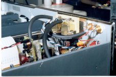
Hi Richard,
in the photo the output tranny of my XB720. They directly couple the dac to RCA, just with 8 68hom resistors and a 1.6n cap.
You can also see the Tent's clock and the discrete regulator for the dac. Dac and clock both has their own PS and regulator.
The sound of this CDP is very good, bur actually I prefer the sound of a Teac VRDS8 with a discrete fet IV and output stage, and Kwak's clock. Much more impressive, expecially in the bass side, but anyway the Sony in his price class is really a very well sounding CDP.
Ciao.
Attachments
To prove that I'm not in hibernation either ")
My Sony CDP-XB930
Ergo
PS. There are some real breaktrough I have made but it'll be for a week or so and then I'll get my own web iste up and I will explain....
My Sony CDP-XB930
Ergo
PS. There are some real breaktrough I have made but it'll be for a week or so and then I'll get my own web iste up and I will explain....
Re: Breakthrough
No, the power for Borbely buffers comes from the original PS. This is a point that needs addiotional tweaking.
The breakthrough is related to combination of CDP-XB930 and Behringer DCX2496 digital crossover. Part of it can be seen in the upper left corner of the pic.
EUVL said:I saw a Tent Clock and 2 Borbely Buffers, right ?
Battery powered ??
Patrick
No, the power for Borbely buffers comes from the original PS. This is a point that needs addiotional tweaking.
The breakthrough is related to combination of CDP-XB930 and Behringer DCX2496 digital crossover. Part of it can be seen in the upper left corner of the pic.
Hi, Michele,
Can you specify the type of transformer, its
wiring, caracteristics-datasheet ?
Wich is the load value you use in the secondary ? Volume pot, input stage ?
Wich ratio is the transformer ?
I recovered an old "Elektor" PCM63 converter, with which I would like to carry out some tests. I will be interested in having a look at your I/V converter, for later, when I will finished this project , so if you can say some more …
Thanks.
Hi Richard.
For the transformers give o look at
http://digilander.libero.it/paeng/magnetics_frame.htm
The I/V converter is a D1 rearranged for singol ended output.
Ciao.
For the transformers give o look at
http://digilander.libero.it/paeng/magnetics_frame.htm
The I/V converter is a D1 rearranged for singol ended output.
Ciao.
I am looking for a test disc, CD and SACD layers, with sine waves at various frequencies and levels, if possible from 0 dBFS to –60 –80 dBFS and silence. I need it to measure and tune the circuit as well as I could.
I have just a "CD test disc" with 1kHz tone at -16 db. I recorded a few years ago a "complete CD test with a digital generator but unfortunately the XB940 doesn't play the CD'R !
I try a Google search ... Nothing in SACD, except some papers from Philips and Sony, both without sales mode indication, and going back to a few years.
If someone knows an easy way to get them... or others !
This W.E. I hope! I will work on the pcb with a complete set of outputs :
Xfr-Balanced, Xfr-Unbalanced, and Fet-direct-Out-Balanced at 0V-dc.
For the transformerless unbalanced circuit, I must design a completely new circuit, it will be for later...
Hi, Alain,
This circuit was just intended to test the VC24+ output, bypassing the current pulse chips, it was the easiest way to do it, I tested the AD826 with and without the current source a few times, and yes there is an improvement. When I tested the AD828 I tested first without the J511 current source, and the sound was the same as the AD826 with the J511, I tried the 828 + the current source and I didn’t notice a real change. As it was not really better, just a little less noisy (2dB) on the test bench, I didn’t went further, or intended more listenings, because I had already in mind the fet design. If the fet design had not been so promising, I would be turned over on this circuit, and carried out more tests, particularly on this point, it is always necessary to repeat the listenings and to be sure of all contacts of my "wishboard" to confirm the improvements.
If I have time soon I will re-test this point, and hold you informed.
These 2 devices are very close, they differ at first sight by their voltage noise and the compensation capacitor, “Cf” on the simplified datasheet diagram.
However you can carry out these tests, just a J511 or a fet device (3/5mA Idss) between the output and V-. For the AD828 devices be careful in supply bypassing and ground connections, they are prone to oscillations.
Nothing! about the SACD test disc ? Post #10
I am working around the power supply for this circuit, the problem is to find the best way to build a suitable one from the existing Sony transformer, I would like an RCRC or LCRC filtering before “reg” but the lack of voltage at the existing transformer 2*13V RMS is not enough for this , maybe a voltage doubler, or changing the transformer, I will work on these various possibilities next days, another possibility would be to install batteries with a simple charger circuit… Patrick => ;-)
I hope scanning soon the XB940 schematics…
I hope scanning soon the XB940 schematics…
Justcallmedad said:I am working around the power supply for this circuit, the problem is to find the best way to build a suitable one from the existing Sony transformer, I would like an RCRC or LCRC filtering before “reg” but the lack of voltage at the existing transformer 2*13V RMS is not enough for this , maybe a voltage doubler, or changing the transformer, I will work on these various possibilities next days, another possibility would be to install batteries with a simple charger circuit… Patrick => ;-)
I hope scanning soon the XB940 schematics…
Hi Justcallmedad,
A CLC filter has neglectable voltage drop. No need to scan the maual as I have sent a complete manual as PDF file to futiboho.
Hi, Elso,
Thanks for the pdf’s, it will be interesting that you attached them in this thread, that could be useful for people interested by this mod.
The LCRC or RCRC is for me the solution to avoid transient current spikes on the transformer, rectifiers, and 1st capacitor, so less noise (wideband noise), very difficult to remove it afterwards.
Of course the L after C helps a lot, but is it enough ? Once you have ”wideband noise” difficult to remove, no ?
Maybe I am wrong, or more precisely, maybe there is no difference in listening, did you tested this (CLC vs. LC or RC) ?
P.S. I liked very much your KISS project !
That file is 7MB big so impossible to post here on the forumJustcallmedad said:Hi, Elso,
Thanks for the pdf’s, it will be interesting that you attached them in this thread, that could be useful for people interested by this mod.
Though the transformer, rectifier and filter caps look like a simple circuit at first glance I am amazed every day how it can be inproved.
The LCRC or RCRC is for me the solution to avoid transient current spikes on the transformer, rectifiers, and 1st capacitor, so less noise (wideband noise), very difficult to remove it afterwards.
Of course the L after C helps a lot, but is it enough ? Once you have ”wideband noise” difficult to remove, no ?
Maybe I am wrong, or more precisely, maybe there is no difference in listening, did you tested this (CLC vs. LC or RC) ?
P.S. I liked very much your KISS project !
I tried a 10 Ohm resistor in series with the choke of the PI-filter in my DAC and it robbed the dynamics form the music.
Then I installed the 10-Ohm between the secondaries and the bridge rectifier and this had the same effect on me.
Interestingly a 1-Ohm resitor at this position is giving less "glare".
The type of transformer and wattage also seem to be important as a toroid has a wide bandwith passing crud (hash) from the mains into your circuit and vice versa. I tried an Amplimo 30 Watt and a Era 30 Watt dual bobbin type and the Era clearly won.
www.amplimo.com
www.era.de
An interestin article in the Audio Amateur pointed me to that.
I also experimented a lot with line filters, including the one advocated by Jon Rish. I could NOT corrobate his findings.
(Ultra)soft recovery diodes also help.
LC RC CRC LCRC RCRC XYZ...
Could you give some more details on your DAC power supply, L/C values, type of regulation (or not) after the Pi filter, choke resistance , did you tried soft recovery vs. schottky ?
Which ultra-soft recovery rectifiers did you use ?
Is it something like your clock7 supply ?
At the light of yours tests, maybe that would mean that this is not the inrush current in the first C that puts the "mess" on the audio, but rather the incoming “noise”, or as you pointed out, the out coming one !
I must say that if I can get good results with CLC and the Sony transformer, it will be the easier and cheapest way to go!
I will carry out some tests on it, this w.e., so the more ideas, the more results to understand what happens.
Have you mod an XB940 ?
Re: LC RC CRC LCRC RCRC XYZ...
http://www.diyaudio.com/forums/showthread.php?s=&threadid=12539&highlight=
I never modded a Sony XB940.
My clock supplies are different from analog supplies used for linestages, DAC-IV-converters and for the TDA1543 I designed a special supply.
It's all on this forum. Press the lousy searchengine!
Most answers can be found in this thread "high speed diodes" started by Fred.Justcallmedad said:Could you give some more details on your DAC power supply, L/C values, type of regulation (or not) after the Pi filter, choke resistance , did you tried soft recovery vs. schottky ?
Which ultra-soft recovery rectifiers did you use ?
Is it something like your clock7 supply ?
At the light of yours tests, maybe that would mean that this is not the inrush current in the first C that puts the "mess" on the audio, but rather the incoming “noise”, or as you pointed out, the out coming one !
I must say that if I can get good results with CLC and the Sony transformer, it will be the easier and cheapest way to go!
I will carry out some tests on it, this w.e., so the more ideas, the more results to understand what happens.
Have you mod an XB940 ?
http://www.diyaudio.com/forums/showthread.php?s=&threadid=12539&highlight=
I never modded a Sony XB940.
My clock supplies are different from analog supplies used for linestages, DAC-IV-converters and for the TDA1543 I designed a special supply.
It's all on this forum. Press the lousy searchengine!
Audio Amateur Article
Hi,
I found back the Audio Amateur article showing a bandwidth graph for the Avel-Lindberg D-3022 toroid flat to nearly 200kHz and a Magnatek FD7-36 nearly 35dB down at that frequency. Please see Audio Amateur volume 4, 1995, page 36. It's the fourth article about the Jung regulator by Gary Galo.
Hi,
I found back the Audio Amateur article showing a bandwidth graph for the Avel-Lindberg D-3022 toroid flat to nearly 200kHz and a Magnatek FD7-36 nearly 35dB down at that frequency. Please see Audio Amateur volume 4, 1995, page 36. It's the fourth article about the Jung regulator by Gary Galo.
- Status
- This old topic is closed. If you want to reopen this topic, contact a moderator using the "Report Post" button.
- Home
- Source & Line
- Digital Source
- Out-stage for Sony CD players.