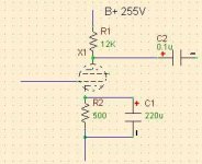
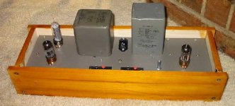
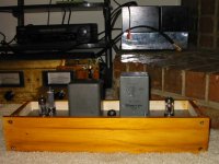
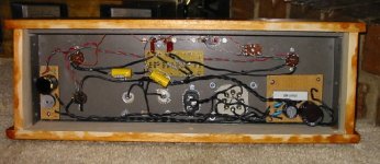
finished this one this afternoon, .. built in a discarded printer splitter aluminum chassis. initial impressions are promising, .. even with a $2 radioshack pot (wired backwards, currently ... and some no name coupling caps)..
rectification is solid state,.. with a damper tube in series to provide slow start
filtering is CLC (22uF - 18H - 220uF) with DC filament heating.
hum is all but absent, courtesy of the big choke. currently in a temporary poplar wood chassis, till i build something a bit more permanent
BTW, .. thanks to all who answered misc. questions along the way (you know who you are)
haven't listened critically, .. but the sound seems to be neutral and more dynamic (biger?) than my previous carver preamp. can't form an objective analysis yet, .. but this is definately good. currently feeding a SS marantz 170DC
looking for suggestions on tweaks etc . ... , ..
how would i know if i need grid stoppers on this one
thinking of CCS on plate, .. but would it also be recommended to use one on the cathode
speaking of cathodes, ..
a. can i (should i ) remove the bypass cap?
b. would a battery bias be an improvement
what're a good choice of not terribly expensive coupling caps and what is a good value to pick (i've seen values all over the board for this component, .. )
do i need resistors from the grid to ground and cap output to ground ?
thanks
Attachments
Hi,
You'd need a o-scope to spot HF oscillation, normally this being an anode follower you shouldn't need any.
If you decide to put one in (100R or upwards), take a carbon comp resistor and solder the body as close to grid of the tube as you can.
Can, yes...but you'll lose some gain and Zout will approximately double.
IME, yes...YMMV.
Yes but the pot is doubling as a gridleakresistor now, still it won't hurt to put a gridleak of say, 1M close to the grid to be safe in case the pot's wiper goes south.
Always put a bleeder behind the output cap unless you fancy bigbanglike turn-on thumps...
Currently the input resistor of the amp is doubling as a bleeder but it isn't recommended practice.
With this circuit you can't really drive neither very low Zin amps nor very long IC runs so I'd recommend in the order of 2-3µF in that position.
Cheers,")
how would i know if i need grid stoppers on this one
You'd need a o-scope to spot HF oscillation, normally this being an anode follower you shouldn't need any.
If you decide to put one in (100R or upwards), take a carbon comp resistor and solder the body as close to grid of the tube as you can.
a. can i (should i ) remove the bypass cap?
Can, yes...but you'll lose some gain and Zout will approximately double.
b. would a battery bias be an improvement
IME, yes...YMMV.
do i need resistors from the grid to ground and cap
output to ground ?
Yes but the pot is doubling as a gridleakresistor now, still it won't hurt to put a gridleak of say, 1M close to the grid to be safe in case the pot's wiper goes south.
Always put a bleeder behind the output cap unless you fancy bigbanglike turn-on thumps...
Currently the input resistor of the amp is doubling as a bleeder but it isn't recommended practice.
(i've seen values all over the board for this component, .. )
With this circuit you can't really drive neither very low Zin amps nor very long IC runs so I'd recommend in the order of 2-3µF in that position.
Cheers,
fdegrove said:
With this circuit you can't really drive neither very low Zin amps nor very long IC runs so I'd recommend in the order of 2-3µF in that position.
Cheers,
Can you elaborate, .. the Zout of this preamp is around 900 Ohm. Shouldn't this be enough to drive love Zin amps, .. and how does the value of the coupling cap related to this consideration?
thanks
Shouldn't this be enough to drive love Zin amps, .. and how does the value of the coupling cap related to this consideration?
Quick calculations with Tube cad show a .1 uF cuppling cap is good to about 15 Hz with a 100K load. This high a 3db point can cause problems with phase shifts in the base.
With a 20k input Z SS amp, its a dismal 75 Hz.
If you know that you are using tube amps with 50k or higher input z, a .47 uF should do. if you want to drive 20k SS amps,
1 uF is minimum (7 Hz) and more may not be out of place IMHO.
HTH;
Doug
DougL said:
Quick calculations with Tube cad show a .1 uF cuppling cap is good to about 15 Hz with a 100K load. This high a 3db point can cause problems with phase shifts in the base.
With a 20k input Z SS amp, its a dismal 75 Hz.
If you know that you are using tube amps with 50k or higher input z, a .47 uF should do. if you want to drive 20k SS amps,
1 uF is minimum (7 Hz) and more may not be out of place IMHO.
HTH;
Doug
thank you, .. i'll put in larger cap and see what happens
The Aeon Film & Foil caps from Michael Percy are a really good value for coupling caps. I also like to use the Kiwame carbon films he carries as well as the Mill's wire wound resistors on the cathodes ( and in the PSU ) of the circuits I build. If you are driving a Tube amp with this preamp you should be able to eliminate the bypass cap with no discernable effects ( except a reduction in gain )to the sonics if you desire. You won't be able to hear the difference with your ears anyway so whatever makes you happy will work just fine. For an adhoc version of your circuit the build looks nice and clean. Good job. Please let us know your opinion of the sound when it is "burned in".
IF NOT YOUR EARS THEN WHAT?
Hi,
You don't hear the cap degrading sonics? I always do...
Anyway it's worth a try and there's probably a little too much gain anyway.
Keep in mind Zout wil be about double the current value: 900 Ohm becomes 1K8 which could be a problem when driving loads smaller than say 20K.
Cheers,
Hi,
You won't be able to hear the difference with your ears anyway so whatever makes you happy will work just fine.
You don't hear the cap degrading sonics? I always do...
Anyway it's worth a try and there's probably a little too much gain anyway.
Keep in mind Zout wil be about double the current value: 900 Ohm becomes 1K8 which could be a problem when driving loads smaller than say 20K.
Cheers,
Attachments
Re: IF NOT YOUR EARS THEN WHAT?
No Frank LOL. I'm not going to presume to claim to have the experienced ear that you do. My opinion and advice was that of a novice. No sarcasm implied, nor I hope, perceived.
fdegrove said:Hi,
You don't hear the cap degrading sonics? I always do...
Anyway it's worth a try and there's probably a little too much gain anyway.
Keep in mind Zout wil be about double the current value: 900 Ohm becomes 1K8 which could be a problem when driving loads smaller than say 20K.
Cheers,
No Frank LOL. I'm not going to presume to claim to have the experienced ear that you do. My opinion and advice was that of a novice. No sarcasm implied, nor I hope, perceived.
Hi,
Nah, of course not....I must say the electrolytics have much improved over the passed 10 years or so.
Thank god for that...
Still, to give a quick and dirty description of the effect: slowed down transient response, slightly blurred treble, bloated soggy bass...amongst others.
OTOH, it is good practice to design one way or the other.
By which I simply mean that the side effects of leaving the cap out aren't just sonic in nature but also have electrical repercussions.
Cheers,
No sarcasm implied, nor I hope, perceived.
Nah, of course not....I must say the electrolytics have much improved over the passed 10 years or so.
Thank god for that...
Still, to give a quick and dirty description of the effect: slowed down transient response, slightly blurred treble, bloated soggy bass...amongst others.
OTOH, it is good practice to design one way or the other.
By which I simply mean that the side effects of leaving the cap out aren't just sonic in nature but also have electrical repercussions.
Cheers,
- Status
- This old topic is closed. If you want to reopen this topic, contact a moderator using the "Report Post" button.
- Home
- Amplifiers
- Tubes / Valves
- yet another 12b4a