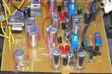
Here's the latest incarnation of the folded cascode, common base I/V converter.
Just finished it, and it's up and running")
The TDA1543 part of this pcb,
with synchronous reclocking of I2S signals,
Tent XO and the digital supplies can be found here,
http://www.diyaudio.com/forums/showthread.php?s=&threadid=23044&highlight=
It's basically unaltered, using VHC logic for synchronous reclocking, several 220u/10V Sanyo Oscon's for bypassing, mixed with 805 SMD combo's of 100n & 10n per Pete Goudreau
Again I settled on 1000u/10V Rubycon ZL with 220u/10V Sanyo Oscon for the TDA1543 supply.
Each chip gets its' own very tiny and very low noise REG101-5 regulator, 805 smd 100n+10n for the BYPASS pin.
I left the DC servo out this time, since my amplifier has one of its own already. Peter Daniel reported some negative influence, even though my simulator THD measurements indicate no ill-effect.
The jfet cascode on the 2nd current sink does improve things, again the THD measurement in the simulator tell me it shouldn't make a difference
Implementing the super-pair brought a small improvement, now the simulator promissed a large improvement
Important lesson learned: DO NOT TRUST SIMULATORS, sorry Jocko, needed to find out for myself...
Riv is a mix of Riken (1.5k), Tantalum (10k) and DALE RN65C (40.2k), Civ is a Philips 1.0n KP
Q2N is 2SC2547E
Q2P is 2SA1085E
all other bjt's are BC549C and BC557B
100u/25V and 470u/25V are Rubycon ZL series
Resistors are small Beyslag series MRS16T
I'll probably leave it this way now, don't have may ideas how to improve it.
Tried the CFP, didn't like it (oscillated at first)
Happy DIY,
Just finished it, and it's up and running
The TDA1543 part of this pcb,
with synchronous reclocking of I2S signals,
Tent XO and the digital supplies can be found here,
http://www.diyaudio.com/forums/showthread.php?s=&threadid=23044&highlight=
It's basically unaltered, using VHC logic for synchronous reclocking, several 220u/10V Sanyo Oscon's for bypassing, mixed with 805 SMD combo's of 100n & 10n per Pete Goudreau
Again I settled on 1000u/10V Rubycon ZL with 220u/10V Sanyo Oscon for the TDA1543 supply.
Each chip gets its' own very tiny and very low noise REG101-5 regulator, 805 smd 100n+10n for the BYPASS pin.
I left the DC servo out this time, since my amplifier has one of its own already. Peter Daniel reported some negative influence, even though my simulator THD measurements indicate no ill-effect.
The jfet cascode on the 2nd current sink does improve things, again the THD measurement in the simulator tell me it shouldn't make a difference
Implementing the super-pair brought a small improvement, now the simulator promissed a large improvement
Important lesson learned: DO NOT TRUST SIMULATORS, sorry Jocko, needed to find out for myself...
Riv is a mix of Riken (1.5k), Tantalum (10k) and DALE RN65C (40.2k), Civ is a Philips 1.0n KP
Q2N is 2SC2547E
Q2P is 2SA1085E
all other bjt's are BC549C and BC557B
100u/25V and 470u/25V are Rubycon ZL series
Resistors are small Beyslag series MRS16T
I'll probably leave it this way now, don't have may ideas how to improve it.
Tried the CFP, didn't like it (oscillated at first)
Happy DIY,
Attachments
Currently I like it a lot, doesn't mean zip to you, I knowPeter Daniel said:So how much better is it, comparing to a previous version? Mostly, is it worth upgrading?
Bit hard to tell, since only yesterday I re-installed the jfet cascode on the previous I/V board.
Did you install that jfet on your board btw ?
I'll let you know in a couple of days.
You could use a 4148 diode, but I used a green LED...think like Christmas treesjean-paul said:Hi Rudolf, is D3 a LED ? I don't think it is but what diode do you use there ?

Why did I ask ?
I only see 4 LED's on the PCB, that's why I ask. In your schematic I see 5 LED's ( 3 green ones and 2 red ones ).
BTW since the servo is omitted maybe it is better to use an output cap + resistor to ground after it ? Could you repeat the adjustment procedure in this thread for those that don't know the Search function ? The Iref resistor for TDA1543 will be 1k2 ?
Did you change your design for TDA5141A like this one as well ?
Many questions but not meant negatively.
Regards,
Jean-Paul
edit: I checked again and I now see that there are 2 LED's D3 in the schematic ...
I only see 4 LED's on the PCB, that's why I ask. In your schematic I see 5 LED's ( 3 green ones and 2 red ones ).
BTW since the servo is omitted maybe it is better to use an output cap + resistor to ground after it ? Could you repeat the adjustment procedure in this thread for those that don't know the Search function ?
The Iref resistor for TDA1543 will be 1k2 ?Did you change your design for TDA5141A like this one as well ?
Many questions but not meant negatively.
Regards,
Jean-Paul
edit: I checked again and I now see that there are 2 LED's D3 in the schematic ...
Bricolo said:What's the difference between a super pair and a CFP?
Douglas Self has one page on his own site that discusses CFP.
“Super pair” was mentioned a few times here at diyAudio.
http://www.diyaudio.com/forums/showthread.php?s=&threadid=13590&highlight=baxandall
Pedja
“Super pair” was mentioned a few times here at diyAudio.
http://www.diyaudio.com/forums/showthread.php?s=&threadid=13590&highlight=baxandall
Pedja
Rudolf,rbroer said:Important lesson learned: DO NOT TRUST SIMULATORS, sorry Jocko, needed to find out for myself...
I rather would do trust in simulators (in reasonable degree, of course, and despite of what Jocko says).
The problem is rather that the relations between the harmonic (and bulk of other types of) distortion and the sound quality are not any simple and we probably know almost nothing about them. Very sad, yes.
Pedja
The disadvantage of the super pair vis a vis the CFP would appear to be the lack of control over Vbe of the output device.
In the CFP this is ably compensated, and if one runs the input device at constant current, the Vbe of this device alone determines the voltage step across the pair from input to output for the entire operating range.
The CFP is veritably the 'monkey atop the elephant', but the super pair's only advantage appears to be current amplification and an input and output at almost the same potential.
This is all subjective, of course, no math.
Agree with you Pedja about the effect of distortion spectra on human perception. Much work needs to be done; until we actually know definitively, 'voicing' will continue to be fashionable.
Cheers,
Hugh
AKSA said:The disadvantage of the super pair vis a vis the CFP would appear to be the lack of control over Vbe of the output device.
In the CFP this is ably compensated, and if one runs the input device at constant current, the Vbe of this device alone determines the voltage step across the pair from input to output for the entire operating range.
The CFP is veritably the 'monkey atop the elephant', but the super pair's only advantage appears to be current amplification and an input and output at almost the same potential.
This is all subjective, of course, no math.
Agree with you Pedja about the effect of distortion spectra on human perception. Much work needs to be done; until we actually know definitively, 'voicing' will continue to be fashionable.
Cheers,
Hugh
Gedday Hugh,
Pedja's schematic and your comments both apply to super pair
configurted as an emitter follower.
However within the context of this thread the super pair
is used as a gnd base stage for I-V open loop. In this case I feel
it has some interesting properties which are very good.
For the initial virtual gnd pair that the dac feeds, the super pair
will result in a more accurate current transfer to the folded
cascode pair compared to single BJT . I think the CFP here would
have equally good current transfer capabilities with a lower
virtual gnd Z which may be an advantage WRT dac OP induced
distortion, however the super pair probably has better transient
performance and settling time due to lower loop gain ( there is
a small loop).
WRT folded cascode super pair, here I think is a nice application
of SP where it has ability to greatly reduce miller C and more
importantly modulation of it. This C modulation will result in
distortion into OP load.
I think a useful thing to try in this circuit would be an additional
super pair current source loading OP on bottom.
Cheers,
Terry
Hi Terry,
Thanks for your post; I didn't even think of the I/V role when I posted, my apologies!
The irony is that I've just completed development of an I/V converter for my next product, a 1702 based DAC! I can clearly see that while a super pair might be very good in this role, there's another consideration.....
The super pair will still vary its Vbe on the output device with varying current input. This won't be controlled, and will give some amplitude modulation of voltage at the output of the DAC which is, of course, bad. A CFP, with the control transistor running in constant current, will drive all current variation into the output device, which will of course vary it's Vbe. But the CFP will accommodate this beautifully!
Of course, we can run the I/V converter at a quiescent many times higher than delta I, thus submerging any non-linearities, but there is elegance in eliminating it entirely if we can.
Rudolf, why have you elevated the base of Q2P to around 3V? This will place the emitter of Q2N, the current injection point, at around 2V5. Is this the design output potential of the DAC? (I guess it must be, half Vcc!)
Nice design.......
Cheers,
Hugh
the super pair might be veiwed as a feedforward shceme that improves Hfe linearity and increases ouput Z / reduces Zcb nonlinearity, but as Hugh points out does nothing to reduce Vbe moduclaiton/input Z as common base amplifier
given that we are told that low Z at the input of the I/V is necessary for low distortion perhaps the CFP should be used at the input with the super pair reserved for the folded cascode output
i expect that the fet cascode of the output current sink is probably as good as it gets and possibly better than the super pair in this position
- Status
- This old topic is closed. If you want to reopen this topic, contact a moderator using the "Report Post" button.
- Home
- Source & Line
- Digital Source
- "Super-Pair" I/V for TDA1543