Diving right into it, negative output impedance can be useful under certain circumstances because it can at least partially compensate for the resistance of the speaker voice coil. If the coil resistance (not impedance) was zero then the speaker would do just exactly what the drive waveform was telling it to do. The fundamental resonance would be flattened out almost completely. The rolling off at low frequencies in a small sealed box would not occur - at least within the cone excursion limits.
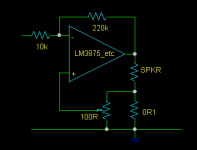
What this cct does is measure the current through the speaker and send back to the non-inverting input a voltage proportional to the voice coil current. This voltage is then amplified in the normal way, in addition to the signal, and it is this extra voltage that will be dropped in the voice coil resistance.
I did make up one of these ccts once before in a different amplifier and if you wind up the pot to far it will gradually slide into instability. It is positive feedback after all. But it does work!
All you need to add to your gainclone or whatever is a low value sensing resistor and a small pot. Tonight I am going to try it myself.
Attachments
Konnichiwa,
And the voice coil resistance is not constant, but signal level dependent. Big problem, Eye Knowz....
NI, been there, done that, got the T-Shirt, NDFG.
Actually, that is chemically pure bovine excrement. Normal electrodynamic drivers are pure current controlled devices and will do anything but what the waveform applied as voltage tells them. If we convert the system to current drive the voice coil resistance becomes irelevant, as does compression and several distortion mechanisms.
The only "price" to pay is that we now need to handle the mechanical resonance of the driver mechanically (for example apperiodic boxes) instead of hiding the mechanical system resonance behind the "damping factor" magical trick.
Actually, with fully compensated voice coil DCR the driver does NOT have a linear response, it is actually a rising response, but rising at a constant rate and thus easily equalised. Of course, as the voicecoil varies in resitance with signal and as it has also material inductance the resulting system is highly unstable. I shot quite a few bass drivers to the lake of fire and sulphur before giving up.
If you want to contol the cone accuratley at high excursion (LF) the best way is still to have a sensor, for anything with modest movement current drive sufficiently above the resonance is an excellent solution.
I have been around this lark in the 1980's, I ended up with a current feed, inverting circuit IC powered (TDA2030) 5.25" wideband driver (no whizzer) covering 200Hz -10KHz, a voltage feed inverting circuit IC powered (TDA2030) modified piezo tweeter (10KHz to as far up as they go) and dual 8" drivers powered from bridged TDA2030 with current booster transistors.
The woofers used a standard (omnidirectional) Electrect Mike capsula as sensor on each driver to sense the pressure. Nowadays I would likely apply the Linkwitz Mod, but I never really played that system extremely loud, only "very loud", so the Mike nonlinearity seems to have not mattered that much.
That system had the kind of dynamics I had with my Horn System (Sorta Klipsch Cornwall, but using all EV Drivers) with a more "HiFi" sound. It would probably be worthwhile building something similar again...
Sayonara
Circlotron said:Diving right into it, negative output impedance can be useful under certain circumstances because it can at least partially compensate for the resistance of the speaker voice coil.
And the voice coil resistance is not constant, but signal level dependent. Big problem, Eye Knowz....
NI, been there, done that, got the T-Shirt, NDFG.
Circlotron said:If the coil resistance (not impedance) was zero then the speaker would do just exactly what the drive waveform was telling it to do.
Actually, that is chemically pure bovine excrement. Normal electrodynamic drivers are pure current controlled devices and will do anything but what the waveform applied as voltage tells them. If we convert the system to current drive the voice coil resistance becomes irelevant, as does compression and several distortion mechanisms.
The only "price" to pay is that we now need to handle the mechanical resonance of the driver mechanically (for example apperiodic boxes) instead of hiding the mechanical system resonance behind the "damping factor" magical trick.
Circlotron said:The fundamental resonance would be flattened out almost completely. The rolling off at low frequencies in a small sealed box would not occur - at least within the cone excursion limits.
Actually, with fully compensated voice coil DCR the driver does NOT have a linear response, it is actually a rising response, but rising at a constant rate and thus easily equalised. Of course, as the voicecoil varies in resitance with signal and as it has also material inductance the resulting system is highly unstable. I shot quite a few bass drivers to the lake of fire and sulphur before giving up.
If you want to contol the cone accuratley at high excursion (LF) the best way is still to have a sensor, for anything with modest movement current drive sufficiently above the resonance is an excellent solution.
I have been around this lark in the 1980's, I ended up with a current feed, inverting circuit IC powered (TDA2030) 5.25" wideband driver (no whizzer) covering 200Hz -10KHz, a voltage feed inverting circuit IC powered (TDA2030) modified piezo tweeter (10KHz to as far up as they go) and dual 8" drivers powered from bridged TDA2030 with current booster transistors.
The woofers used a standard (omnidirectional) Electrect Mike capsula as sensor on each driver to sense the pressure. Nowadays I would likely apply the Linkwitz Mod, but I never really played that system extremely loud, only "very loud", so the Mike nonlinearity seems to have not mattered that much.
That system had the kind of dynamics I had with my Horn System (Sorta Klipsch Cornwall, but using all EV Drivers) with a more "HiFi" sound. It would probably be worthwhile building something similar again...
Sayonara
Raka said:Not for you, Circlotron, but for all the newbies like me, there is an article about this in the ESP pages that could make a good reading.
Yup, he pretty much sums up the use of negative impedance in Effects of Source Impedance on Loudspeakers where he says:
Negative impedance does exactly what it implies - when the load is increased (with a lower impedance), the signal applied to the load increases (i.e. the exact opposite of what normally happens). This results in an intrinsically unstable system, and great care must be taken to prevent the creation of an oscillator.
The performance of this combination is completely unacceptable in every sense of the term. This combination could never be used in practice, for any reason. There is a vicious attack, with the signal doing something at a frequency completely unrelated to the input signal - unrelated in any way that I can determine, at least.
Considerable ringing is apparent (again at an unrelated frequency) when the signal is removed. This is highly visible and audible, and the sound of the attack and decay is grossly inferior to any other combination. The others (using positive impedance) have some character, but it is related to the signal, and makes some sort of musical sense.
se
As I mentioned in one or more articles on these pages, I have never found a cone speaker that "likes" negative impedance. Horn compression drivers seem quite happy and this is a test that I may now be forced to perform to find out what it does, and how it affects the sound (other than an apparent improvement in bandwidth).
From the link at Rod's home page http://www.sound.westhost.com/z-effects.htm
As I understand negative impedance is especially good for bass reflex woofer, not so good for a ordinary fullrange speaker. It must be carefully tuned!
The "negative" properties is to cancel out the resistance (losses) in the woofer element and the cables. This cancellation makes it easier to control both the helmholtz and the mechanical resonance.
Konnichiwa,
Actually, as usual poor understanding.
If you redraw (and disaggregate) the circuit you find that NI that completely cancels the DCR of the Voicecoil actually becomes a simple feedback circuit that uses the voicecoil as sensor. The signal from the voicecoil needs to be integrated to give correct response.
But as said, because the DCR is heavily signal dependent and because of the non-linearity of the voicecoil as sensor (BACK EMF) this is a really stupid way of doing it. I tried it way back. It is STUPID.
I repeat, the easiest way to control your woofer is to generate the feedback signal with a cheap modded panasonic electret mike capsula. As SL esimates, the WM60 modded can handle 141db. If you place the Mike close to the cone (say 12.5cm) you have more SPL than @ 1m.
With 141db @ 12.5cm it will be around 123db @ 1m, meaning for HiFi speakers this mike makes a perfectly sensible sensor (few HiFi Drivers produce > 123db/1m).
With 12.5cm distance to the cone you will have 90 degrees phaseshift @ 860Hz. So if you want to control a woofer only (where it makes sense) you will be fine. Then use a suitable Midrange system and feed it with current drive for eliminating compression and drastically reducing distortion.
For a fullrange driver I suspect a realtime laser position sensing system would be needed probably on the voicecoil itself to work over a wide enough bandwidth.
Sayonara
peranders said:
As I understand negative impedance is especially good for bass reflex woofer, not so good for a ordinary fullrange speaker. It must be carefully tuned!
The "negative" properties is to cancel out the resistance (losses) in the woofer element and the cables. This cancellation makes it easier to control both the helmholtz and the mechanical resonance.
Actually, as usual poor understanding.
If you redraw (and disaggregate) the circuit you find that NI that completely cancels the DCR of the Voicecoil actually becomes a simple feedback circuit that uses the voicecoil as sensor. The signal from the voicecoil needs to be integrated to give correct response.
But as said, because the DCR is heavily signal dependent and because of the non-linearity of the voicecoil as sensor (BACK EMF) this is a really stupid way of doing it. I tried it way back. It is STUPID.
I repeat, the easiest way to control your woofer is to generate the feedback signal with a cheap modded panasonic electret mike capsula. As SL esimates, the WM60 modded can handle 141db. If you place the Mike close to the cone (say 12.5cm) you have more SPL than @ 1m.
With 141db @ 12.5cm it will be around 123db @ 1m, meaning for HiFi speakers this mike makes a perfectly sensible sensor (few HiFi Drivers produce > 123db/1m).
With 12.5cm distance to the cone you will have 90 degrees phaseshift @ 860Hz. So if you want to control a woofer only (where it makes sense) you will be fine. Then use a suitable Midrange system and feed it with current drive for eliminating compression and drastically reducing distortion.
For a fullrange driver I suspect a realtime laser position sensing system would be needed probably on the voicecoil itself to work over a wide enough bandwidth.
Sayonara
You can mount your mic onto the woofer cone (best place would be the edge of the dustcap) with the mic's diaphragm looking sideways.
B&M were the first ones who did this AFIK. A current sub using this is the Manger "Subsonice".
Because you are in the speaker's nearfield (also with 12.5 cm), the 6dB/distance-doubling rule wouldn't exactly apply and the sound-pressure at the microphoine might be even a bit less than 141 dB for 123 dB @ 1m.
If you ground the non-inverting input in Graham's circuit and put feedback to the inverting input you get current drive. Its pros and cons have already led to lively discussions on this forum !
Regards
Charles
Konnichiwa,
Nice to know. Back in the 80's I simply stuck the Mike on a bridge in front of the Dustcap, pointing inwards.... Worked quite fine. Once it was sufficiently debugged it was very stable, unlike any of the voicecoil based sensing systems (NI, Bridge....) which all worked fine untill the weather chaged or you turned up the Volume, upon which occasion thing wend reliably BANG....
I know, but I could not be bothered to calculate accuratly, so I just assumed "worst case".... ;-)
Yes, indeed. On both counts.
Sayonara
phase_accurate said:You can mount your mic onto the woofer cone (best place would be the edge of the dustcap) with the mic's diaphragm looking sideways.
B&M were the first ones who did this AFIK. A current sub using this is the Manger "Subsonice".
Nice to know. Back in the 80's I simply stuck the Mike on a bridge in front of the Dustcap, pointing inwards.... Worked quite fine. Once it was sufficiently debugged it was very stable, unlike any of the voicecoil based sensing systems (NI, Bridge....) which all worked fine untill the weather chaged or you turned up the Volume, upon which occasion thing wend reliably BANG....
phase_accurate said:Because you are in the speaker's nearfield (also with 12.5 cm), the 6dB/distance-doubling rule wouldn't exactly apply and the sound-pressure at the microphoine might be even a bit less than 141 dB for 123 dB @ 1m.
I know, but I could not be bothered to calculate accuratly, so I just assumed "worst case".... ;-)
phase_accurate said:If you ground the non-inverting input in Graham's circuit and put feedback to the inverting input you get current drive. Its pros and cons have already led to lively discussions on this forum !
Yes, indeed. On both counts.
Sayonara
Re: Re: Gainclone with negative output impedance
quote:
Originally posted by Circlotron
If the coil resistance (not impedance) was zero then the speaker would do just exactly what the drive waveform was telling it to do.
1/ Well, yes and no. If the speaker and whatever is driving it both have zero resistance then if the cone becomes difficult to drive at any point then it will try and move somewhat less. This will cause it's self-generated (back?) emf to fall below the driving emf therefore allowing LOTS of current to flow (no resistance remember) causing LOTS of extra mechanical force to be applied.
In theory, this should make the cone follow the drive =voltage= exactly. The resulting drive *current* would be proportional to how hard the cone needs to be pushed to maintain it's correct position to follow the signal at any given moment.
2/ After playing with it for a while, I have decided that this negative resistance thing is a rotten idea!
3/ The electret microphone feedback thing is something I must try. However, for a bass reflex setup I think a good location for the mic would be halfway between the speaker and the port so it hears a bit of both, not from the speaker only as you would do with a sealed system.
quote:
Originally posted by Circlotron
If the coil resistance (not impedance) was zero then the speaker would do just exactly what the drive waveform was telling it to do.
Kuei Yang Wang said:Actually, that is chemically pure bovine excrement. Normal electrodynamic drivers are pure current controlled devices and will do anything but what the waveform applied as voltage tells them. If we convert the system to current drive the voice coil resistance becomes irelevant, as does compression and several distortion mechanisms.Sayonara
1/ Well, yes and no. If the speaker and whatever is driving it both have zero resistance then if the cone becomes difficult to drive at any point then it will try and move somewhat less. This will cause it's self-generated (back?) emf to fall below the driving emf therefore allowing LOTS of current to flow (no resistance remember) causing LOTS of extra mechanical force to be applied.
In theory, this should make the cone follow the drive =voltage= exactly. The resulting drive *current* would be proportional to how hard the cone needs to be pushed to maintain it's correct position to follow the signal at any given moment.
2/ After playing with it for a while, I have decided that this negative resistance thing is a rotten idea!
3/ The electret microphone feedback thing is something I must try. However, for a bass reflex setup I think a good location for the mic would be halfway between the speaker and the port so it hears a bit of both, not from the speaker only as you would do with a sealed system.
Being a fourth-order sytem, a reflex system is quite complicated for MFB to be applyed, though not impossible:
http://www.meyersound.com/products/studioseries/x-10/pdfs/x-10_ds.pdf
Regards
Charles
http://www.meyersound.com/products/studioseries/x-10/pdfs/x-10_ds.pdf
Regards
Charles
Re: Re: Re: Gainclone with negative output impedance
Konnichiwa,
But the Speakers voicecoil DCR is not zero and adding negative resistance external is not the same thing, except in high level abstrations in textbooks....
Only if the driver is already perfect (or rather ideal), in which case it will do that anyway....
Well, I found the same....
One warning, while developing use a high value resistor in series with the Drivers. This prevents them going to palestine (over the Jordan) when the system becomes unstable. It's still feedback and hence inherently unstable!!!
You can make it work for reflex (Meyer has been mentioned), but I would simply seal of dipole the woofah suckah....
Sayonara
Konnichiwa,
Circlotron said:1/ Well, yes and no. If the speaker and whatever is driving it both have zero resistance then if the cone becomes difficult to drive at any point then it will try and move somewhat less. This will cause it's self-generated (back?) emf to fall below the driving emf therefore allowing LOTS of current to flow (no resistance remember) causing LOTS of extra mechanical force to be applied.
But the Speakers voicecoil DCR is not zero and adding negative resistance external is not the same thing, except in high level abstrations in textbooks....
Circlotron said:In theory, this should make the cone follow the drive =voltage= exactly.
Only if the driver is already perfect (or rather ideal), in which case it will do that anyway....
Circlotron said:2/ After playing with it for a while, I have decided that this negative resistance thing is a rotten idea!
Well, I found the same....
Circlotron said:3/ The electret microphone feedback thing is something I must try.
One warning, while developing use a high value resistor in series with the Drivers. This prevents them going to palestine (over the Jordan) when the system becomes unstable. It's still feedback and hence inherently unstable!!!
Circlotron said:However, for a bass reflex setup I think a good location for the mic would be halfway between the speaker and the port so it hears a bit of both, not from the speaker only as you would do with a sealed system.
You can make it work for reflex (Meyer has been mentioned), but I would simply seal of dipole the woofah suckah....
Sayonara
Sensor element at a distanse from the driver?? Don't think so.
speed of sound/ distanse gives the freq of your vavelenght, and 1/freq is time. Things at the element has already happend long before you'r measuring-signal is abt to respond. Unless you are using WERRY!!! low cutoff freq ( low pole) you ask for instability.
speed of sound/ distanse gives the freq of your vavelenght, and 1/freq is time. Things at the element has already happend long before you'r measuring-signal is abt to respond. Unless you are using WERRY!!! low cutoff freq ( low pole) you ask for instability.
Konnichiwa,
Well, I got it stable with around 2cm distance to the cone (so the sensor would not impede the movement of the cone) with a single 1st order pole inside the feedback loop probably at around 300Hz (this was many years ago and memory is hazy, the then active speakers I worked on where lost in the depth of time) and about 12-20db NFB IIRC. So it is not a huge problem....
Just like stabilising any other feedback loop, just look where the distance gives you 90degrees phaseshift and place the pole for the Amplifier/Speaker system inside the loop at this frequency or lower and you will be fine.
Obviously you won't easily get a working NFB loop to work above a few 100Hz to a few KHz, but you don't need to. For midrange and treble current feed works great, sounds great and measures very well, so as it appears good in all domains it IS GOOD.
Sayonara
Konrad said:Sensor element at a distanse from the driver?? Don't think so.
speed of sound/ distanse gives the freq of your vavelenght, and 1/freq is time. Things at the element has already happend long before you'r measuring-signal is abt to respond. Unless you are using WERRY!!! low cutoff freq ( low pole) you ask for instability.
Well, I got it stable with around 2cm distance to the cone (so the sensor would not impede the movement of the cone) with a single 1st order pole inside the feedback loop probably at around 300Hz (this was many years ago and memory is hazy, the then active speakers I worked on where lost in the depth of time) and about 12-20db NFB IIRC. So it is not a huge problem....
Just like stabilising any other feedback loop, just look where the distance gives you 90degrees phaseshift and place the pole for the Amplifier/Speaker system inside the loop at this frequency or lower and you will be fine.
Obviously you won't easily get a working NFB loop to work above a few 100Hz to a few KHz, but you don't need to. For midrange and treble current feed works great, sounds great and measures very well, so as it appears good in all domains it IS GOOD.
Sayonara
speed of sound/ distanse gives the freq of your vavelenght, and 1/freq is time.
That's where mounting the mic on the driver has it's merits.
Regards
Charles
I realize this is an old thread but I'm guessing there are others out there who might stumble upon it and give up for the wrong reasons. Perhaps the thread went off-topic too soon for anyone to comment.
I recently stumbled upon this thread, built the circuit and found that it didn't work.
So I took a closer look.
IIANM, the circuit diagram in the first post does not fit the description...
Please correct me if I'm wrong. It should read:
This voltage is then added to the amplified inverted signal.
I recently stumbled upon this thread, built the circuit and found that it didn't work.
So I took a closer look.
IIANM, the circuit diagram in the first post does not fit the description...
That is what the circuit was supposed to do but I believe it does something else.What this cct does is measure the current through the speaker and send back to the non-inverting input a voltage proportional to the voice coil current. This voltage is then amplified in the normal way, in addition to the signal, and it is this extra voltage that will be dropped in the voice coil resistance.
Please correct me if I'm wrong. It should read:
This voltage is then added to the amplified inverted signal.
No, the original description was correct. Imagine that there is 0V input signal, so 0V at the output would put 0V at the non-inverting input and the op amp is happy. If the input suddenly went to 1V the output would try to swing negative to match the inverting input voltage to the non-inverting input voltage. This causes the voltage at the non-inverting input to go below 0V. It is the differential input voltage that is amplified, so the voltage from the voice coil current is amplified in addition to the signal.
Last edited:
Thanks for the correction and explanation, Brian.
I find it quiet easy to get confused with some of these circuits but I'm back on track now.
Playing with this circuit it is quite a fun exercise for me.
I personally disagree with those who say that negative output impedance is a bad idea.
The results so far are certainly positive in terms of my audio preferences.
Agreed, it is not as good as having a sensor mounted to the voice-coil but it is much simpler and it's better than nothing.
- Status
- This old topic is closed. If you want to reopen this topic, contact a moderator using the "Report Post" button.
- Home
- Amplifiers
- Chip Amps
- Gainclone with negative output impedance