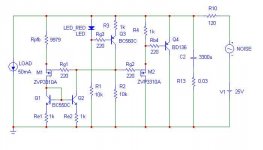
Here is a new shunt power regulator I have developed (and built) for my MC RIAA preamp.
Tomorrow I will leave to Greece for a camping holiday, expecting to have no Internet connection there. Therefore I leave it to the experts to find out how this circuit works and to explain it to the forum (who takes the challenge?).
Note that Rpfb is a variable resistor and must be adjusted for minimising the remaining ripple (therefore the strange value in the simulation).
I hope the attachment is OK.
Cheers,
Gerhard
Attachments
Being back from my holiday, I see some 100 views on this thread, but - strangely enough - no single reply.
In the meantime I was not satisfied with the high frequency performance of the circuit and made some modifications. I have not yet built the new version, but the spice simulation is promising.
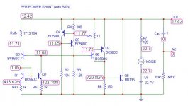
Here is the explanation how the circuit works (V1 and NOISE model the unregulated DC):
The current source Q4/Q5, together with R3, define the regulated voltage, driving the output stage Q6-Q8.
Q3 + the current mirror Q1/Q2 are an error correction amplifier cancelling the distortion of the output stage by adjustment of the variable resistance Rpfb. Note that this is NOT NFB (which reduces distortion by a certain factor), but real cancellation; I will show this in my next post.
You can also see this stage as a negative resistance of -1.8k parallel to the output stage input. Simple math shows that the result is independant of the output stage gain (and therefore of its distortions) if
- the output stage has infinite input impedance,
- the current source is perfect,
- the error correction amplifier is linear and has a constant output impedance.
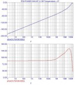
This is not the case in practice, but the performance is outstanding nevertheless (regulation factor of 170dB at 1Hz and 142dB at 100Hz, falling with 6dB/oct).
Stay tuned ... Simulation results will follow.
In the meantime I was not satisfied with the high frequency performance of the circuit and made some modifications. I have not yet built the new version, but the spice simulation is promising.
Here is the explanation how the circuit works (V1 and NOISE model the unregulated DC):
The current source Q4/Q5, together with R3, define the regulated voltage, driving the output stage Q6-Q8.
Q3 + the current mirror Q1/Q2 are an error correction amplifier cancelling the distortion of the output stage by adjustment of the variable resistance Rpfb. Note that this is NOT NFB (which reduces distortion by a certain factor), but real cancellation; I will show this in my next post.
You can also see this stage as a negative resistance of -1.8k parallel to the output stage input. Simple math shows that the result is independant of the output stage gain (and therefore of its distortions) if
- the output stage has infinite input impedance,
- the current source is perfect,
- the error correction amplifier is linear and has a constant output impedance.
This is not the case in practice, but the performance is outstanding nevertheless (regulation factor of 170dB at 1Hz and 142dB at 100Hz, falling with 6dB/oct).
Stay tuned ... Simulation results will follow.
Attachments
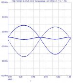
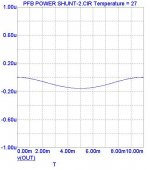
... and here the regulated output at 1Hz (with +-1 V pp unregulated ripple).
The middle waveform is with optimal Rpfb and shows about 6nV ripple (170dB regulation, which is worse by a factor of 10 compared to the small signal analysis result of about 190dB).
The other two waveforms result from under- and over-regulation (Rpfb sligthly too big / too small). Over-regulation actually results in changing the sign of the harmonics; you can use this in an amplifier for changing a compressing 3rd harmonic to an expanding one (Nelson Pass wrote in another thread some weeks ago, that he never saw such a type of distortion. Here is a method to create it).
Attachments
... and here for completeness the waveform for 100Hz. You see the phase shift of 90 degrees as predicted by the AC analysis.
So let's start the discussion. Probably somebody wants to built this shunt regulator and give feedback about the sonic performance. It works fine (the version posted first) with my MC preamp.
Those skilled in the art will know how to make a layout preserving the performance of the circuit and where to add some base blocker resistors. Adding a bypass capacitor (with some 10mOhms ESR) to the shunt will enhance the high frequency performance, which falls by 6dB/oct.
Cheers,
Gerhard
Attachments
- Status
- This old topic is closed. If you want to reopen this topic, contact a moderator using the "Report Post" button.